05 / Hardware
Enclosure Hardware and PEM Fastener Installation
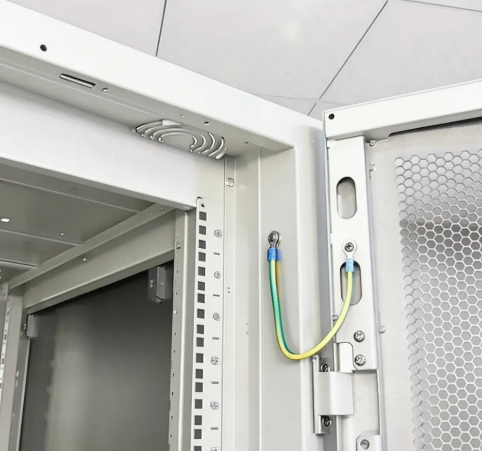
Self-clinching fasteners, studs, hinges, locks, mounting rails and grounding points are planned as part of the enclosure route, not treated as last-minute accessories.
Scope
What This Capability Covers
Inserted hardware affects hole size, sheet thickness, installation side, tool access, coating masks and assembly sequence. The BOM and drawing should identify the exact hardware reference and functional interface. Substitutions are discussed with the buyer rather than assumed.
Manufacturing route
How the Work Is Controlled
- 01
Compare the hardware BOM with drawing callouts
- 02
Confirm prepared holes and installation direction
- 03
Install with controlled tooling and visual checks
- 04
Protect threads and contact areas through finishing
- 05
Verify mating hardware and accessory count at assembly
Engineering checkpoints
Where OEM Projects Usually Need Clear Decisions
These points are reviewed against the real part and the buyer’s acceptance requirements.
Sheet compatibility
Fastener choice must suit the actual material, thickness and load requirement.
Coating sequence
Installing or masking at the wrong stage can damage finish or block electrical contact.
Grounding details
Uncoated contact surfaces, conductors and attachment points need explicit drawing or BOM definition.
Service access
Locks, hinges and removable panels should remain reachable after equipment installation.
Buyer input
What to Include in Your RFQ
Clear project information allows engineering questions, price and timing to be based on the same scope.
- Hardware BOM with manufacturer references
- Installation side and orientation
- Torque, pull-out or functional test requirements
- Grounding and masked-area drawings
- Buyer-supplied component list
Discuss a real project
Let the Drawing Define the Process and Acceptance Plan
Send the controlled files, quantities and application context. We will identify missing information and prepare a practical basis for quotation.