
Design effective custom gauges for sheet metal inspection. Learn about go/no-go gauges, functional gauges, gauge materials, and design best practices.
Introduction
Custom gauges provide fast, reliable inspection of specific features on sheet metal parts. They are essential for high-volume production where 100% inspection is required. At Fulei Metal, we design and build custom gauges for efficient and accurate inspection of our products.
What is a Gauge?
Definition
A gauge is a inspection tool that verifies whether a part feature meets specification without providing a numerical measurement. It gives a pass/fail result. Gauges are faster than measurement tools for production inspection.
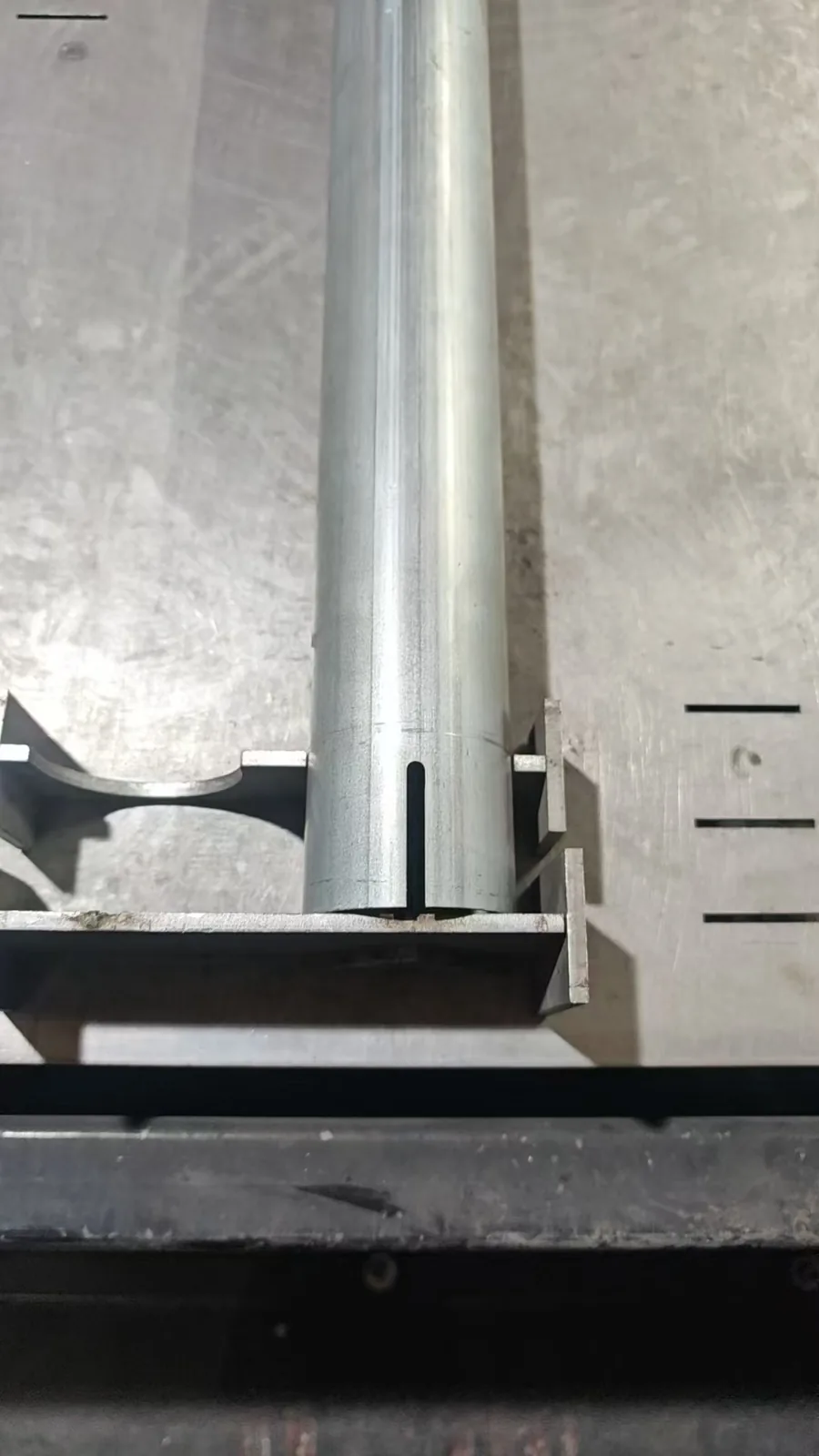
Why Use Gauges?
Speed: gauge inspection is faster than measurement. Simplicity: no reading or interpretation required. Consistency: less operator-dependent than measurement. Cost-effective: low cost per inspection for high volume. 100% inspection: enables inspection of every part.
Gauge Types
Go/no-go gauge: verifies a dimension is within specification. Functional gauge: verifies that a part will assemble with mating parts. Receiver gauge: simulates the mating part. Template gauge: checks a profile or shape. Checking fixture: holds part and checks multiple features.
Go/No-Go Gauges
Principle
Go gauge: should fit or pass through the feature being inspected. Verifies the feature is not too small (for holes) or too large (for shafts). No-go gauge: should not fit or pass through. Verifies the feature is not too large (for holes) or too small (for shafts). If go fits and no-go does not fit, the feature is within specification.
Pin Gauges for Holes
Go pin: at minimum hole diameter. No-go pin: at maximum hole diameter. If go pin enters and no-go pin does not, hole is within tolerance. Available in standard sets or custom sizes.
Ring Gauges for Shafts
Go ring: at maximum shaft diameter. No-go ring: at minimum shaft diameter. If go ring fits and no-go ring does not, shaft is within tolerance.
Snap Gauges
For external dimensions. Adjustable or fixed. Go and no-go anvils. Quick check of external dimensions. Suitable for: thickness, width, diameter.
Gap Gauges
For checking gaps and clearances. Fixed or adjustable. Verify gap is within specification. Suitable for: bend gaps, assembly clearances.
Functional Gauges
What is a Functional Gauge?
A functional gauge verifies that a part will perform its function, typically by simulating the mating part. It checks multiple features simultaneously. It verifies position, orientation, and size together.
Pin Location Gauges
Verify hole pattern position. Gauge pins at nominal hole positions. Pins sized at MMC (maximum material condition) minus position tolerance. If all pins enter holes simultaneously, the hole pattern is within position tolerance.
Profile Gauges
Verify part profile. Gauge profile cut to nominal shape minus profile tolerance. If part fits within gauge, profile is within tolerance. Suitable for: formed profiles, complex edges.
Assembly Simulation Gauges
Simulate mating part assembly. Verify part will assemble correctly. Check critical interfaces. Identify interference or clearance issues.
Checking Fixtures
What is a Checking Fixture?
A checking fixture holds the part in a defined position and provides measurement reference for multiple features. It may include: locating pins, clamping mechanism, measurement surfaces, dial indicators, go/no-go gauges.
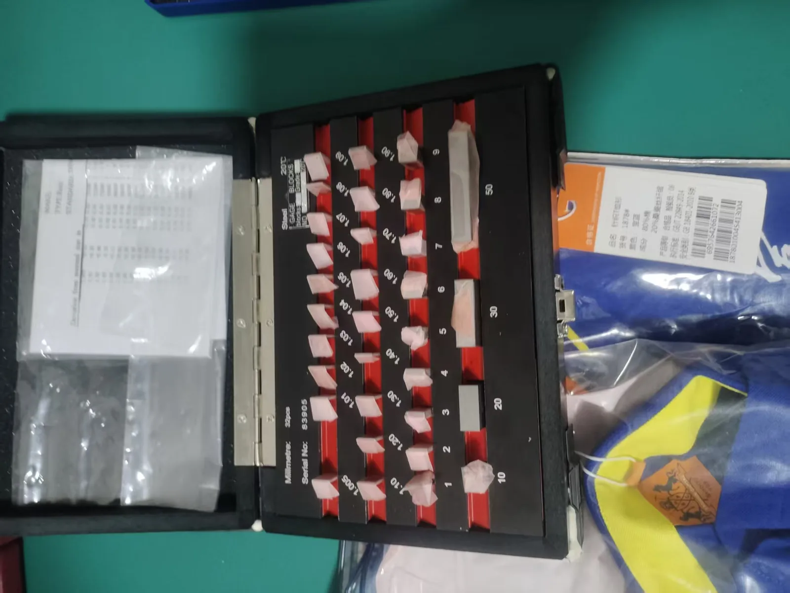
Fixture Components
Locating pins: position the part. Clamps: hold the part firmly. Measurement surfaces: reference for dial indicators. Dial indicators: measure deviations. Go/no-go pins: verify hole positions. Gap gauges: verify clearances.
Checking Fixture Design
Define locating strategy: 3-2-1 locating principle. Select clamping method: quick-action clamps. Determine measurement features: what needs to be checked. Select measurement method: dial indicator, go/no-go, visual. Design for operator access. Design for part loading and unloading.
Gauge Design Principles
Gauge Tolerance
Gauge tolerance is typically 10% of the part tolerance. Go gauge: at the tolerance limit minus gauge tolerance. No-go gauge: at the tolerance limit plus gauge tolerance. This ensures that borderline parts are rejected. Gauge maker’s tolerance is specified in standards.
Wear Allowance
Gauges wear with use. Allowance for wear: gauges are made at the limit that allows for wear. Go gauges: made slightly larger (for holes) to allow for wear. No-go gauges: typically no wear allowance as they do not enter the feature.
Gauge Materials
Tool steel: hardened and ground, for precision gauges. Long wearing. Higher cost. Bearing steel: for pin gauges. Hard and wear-resistant. Carbide: for high-wear surfaces. Very long wearing. Higher cost. Aluminum: for non-critical gauge components. Light weight. Stainless steel: for gauges in corrosive environments.
Gauge Marking
Mark gauges with: gauge ID, part number, feature being checked, go/no-go identification, gauge size, date manufactured. Permanent marking: engraving or etching. Color coding: green for go, red for no-go.
Gauge Design Process
Step 1: Define Requirements
Identify: feature to be inspected, tolerance, inspection rate, operator skill level, environment. Determine if gauge is appropriate: high volume, repetitive inspection, pass/fail acceptable.
Step 2: Determine Gauge Type
Select gauge type based on: feature type (hole, shaft, gap, profile), tolerance, production volume, inspection method. Go/no-go for simple features. Functional gauge for position and assembly. Checking fixture for multiple features.
Step 3: Calculate Gauge Dimensions
Calculate go and no-go dimensions. Apply gauge maker’s tolerance. Apply wear allowance. Verify gauge dimensions will correctly accept good parts and reject bad parts.
Step 4: Design Gauge
Design gauge body: material, size, shape. Design locating features: how gauge positions on part. Design checking features: pins, surfaces, indicators. Design for manufacturing: can the gauge be made? Design for ergonomics: easy to use.
Step 5: Manufacture Gauge
Machine gauge components. Heat treat if needed. Grind to final dimensions. Assemble gauge. Verify gauge dimensions.
Step 6: Verify Gauge
Gauge R&R study: verify gauge produces consistent results. Test with known good and bad parts. Verify gauge correctly accepts good parts. Verify gauge correctly rejects bad parts. Document verification results.
Step 7: Implement and Maintain
Train operators on gauge use. Establish calibration schedule. Track gauge wear. Re-calibrate or replace worn gauges. Document inspection results.
Gauge Maintenance
Cleaning
Clean gauges after each use. Remove dirt, oil, and debris. Use lint-free cloth. Solvent if needed. Store in protective case.
Calibration
Regular calibration: verify gauge dimensions. Frequency: based on usage and wear. Use calibrated measurement equipment. Maintain calibration records.
Wear Monitoring
Track gauge usage. Inspect for wear periodically. Measure critical dimensions. Replace or rework worn gauges. Maintain wear records.
Storage
Store in protective cases. Protected from dust, moisture, and damage. Organized storage: easy to find. Temperature-controlled environment for precision gauges.
Advantages and Limitations
Advantages
Fast inspection: quicker than measurement tools. Simple operation: minimal training required. Consistent: not operator-dependent. 100% inspection: every part can be checked. Cost-effective: low cost per inspection for high volume.
Limitations
Pass/fail only: no numerical value. Does not show trend: cannot track process drift. Limited to designed feature: one gauge per feature. Upfront cost: gauge design and manufacture. Wear: gauges wear and need maintenance. Not suitable for: low volume, prototyping, variable features.
At Fulei Metal
Our gauge capabilities include: custom gauge design for specific products. Go/no-go pin gauges for hole inspection. Functional gauges for assembly verification. Checking fixtures for complex parts. Gauge R&R studies. Gauge calibration and maintenance. We design and build gauges that enable efficient, reliable inspection for our production parts.
Conclusion
Custom gauges are essential for efficient inspection in sheet metal manufacturing. At Fulei Metal, our gauge design and manufacturing capabilities enable us to inspect products quickly and reliably, ensuring consistent quality for our global clients.
Send drawings and we will check them against our quality inspection service capability before quoting. You can also see how this fits into our custom sheet metal fabrication work, or read Outgoing Inspection first if you are still comparing options.
Gauge Types and What Each One Is For
Production gauges exist to make a repeat decision quickly, not to produce a measurement. Choose the wrong type and you get either a gauge that cannot decide anything, or one that rejects good parts.
| Gauge type | Confirms | Design point that makes or breaks it |
|---|---|---|
| Go / no-go plug gauge | That a hole is inside its diameter limits | The go side must pass and the no-go side must not enter; both sides need regular wear checking |
| Hole-position gauge | That a pattern of holes will accept the mating part | The gauge must be built to the mating part’s true position, not to the nominal drawing dimensions |
| Profile or form gauge | That a formed profile matches the intended shape at defined sections | Sections must be chosen where the part is functionally located, not where it is convenient to check |
| Weld assembly gauge | That a welded frame will accept the components that bolt to it | It should check the interfaces that matter after welding distortion, not the nominal frame dimensions |
| Attribute check fixture | Presence, orientation and accessibility in one operation | Fast to use and unambiguous, but it tells you nothing about how far out a failed part is |
The design rule: a gauge answers a yes/no question. If your acceptance criterion is a number rather than a limit, a gauge is the wrong tool and you want a measurement instead.
Frequently Asked Questions
Should incoming inspection of a purchased part use a gauge or a CMM?
If you are checking a defined interface — does the bracket bolt up, does the panel fit the frame — a gauge gives a faster and more repeatable answer. If you need to know how far out a part is and in which direction, use measurement. Many buyers run the gauge routinely and send samples to measurement when it fails.
How often does a gauge need re-verification?
It depends on wear. A gauge used on hundreds of parts a day drifts far faster than one used weekly. The practical approach is periodic verification against the master, plus verification after any incident and whenever the gauge starts disagreeing with a measurement. The interval should come from observed drift, not from a default printed in a procedure.
Can a gauge replace dimensional inspection entirely?
No, and it should not try to. A gauge confirms a feature is inside its limits; it does not tell you the part is as drawn. First article dimensional inspection still happens, and the gauge covers the running checks between first article and pre-shipment.
Questions about a specific part are usually faster to answer against the drawing — send it through the route below.
Related at Fulei Metal: sheet metal quality inspection service · first article inspection (FAI)