
Master dimensional inspection for sheet metal parts. Learn about measurement tools, techniques, tolerance verification, and best practices for accurate inspection.
Introduction
Dimensional inspection verifies that sheet metal parts meet the dimensional specifications on engineering drawings. Accurate dimensional inspection is essential for ensuring part fit, function, and interchangeability. At Fulei Metal, we implement comprehensive dimensional inspection throughout our manufacturing process.
Why Dimensional Inspection Matters
Quality Assurance
Dimensional inspection confirms that parts meet specifications. It prevents non-conforming parts from reaching assembly or the customer. It provides objective evidence of quality. It builds customer confidence.
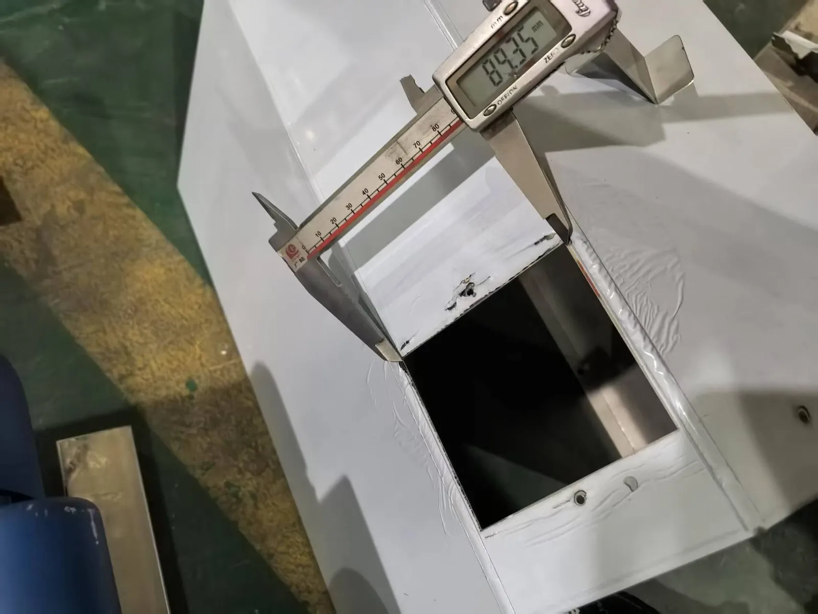
Process Control
Dimensional inspection data reveals process performance. Trends indicate process drift. Variation indicates process capability. Inspection data drives process improvement.
Cost Reduction
Catching dimensional errors early reduces scrap and rework. Preventing non-conforming parts from reaching assembly reduces assembly problems. Avoiding customer returns protects reputation and reduces warranty costs.
Measurement Tools
Basic Measurement Tools
Steel rule: for quick, approximate measurements. Accuracy: plus or minus 0.5mm. Suitable for non-critical dimensions. Tape measure: for large dimensions. Accuracy: plus or minus 1mm. Calipers: digital, dial, or vernier. Accuracy: plus or minus 0.02mm for digital. Measures: outer dimensions, inner dimensions, depth.
Precision Measurement Tools
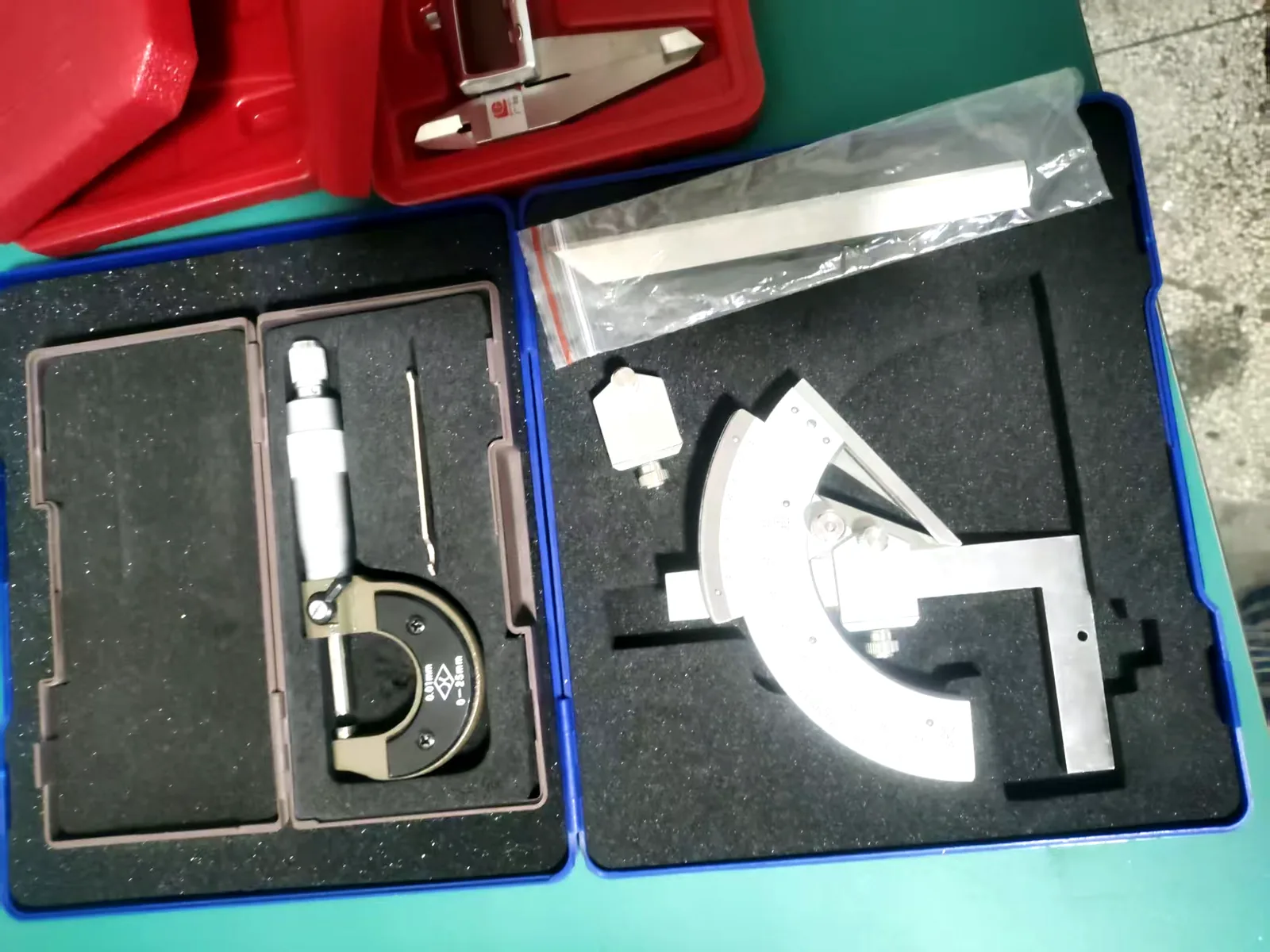
Micrometer: for precise measurement of thickness and diameter. Accuracy: plus or minus 0.001mm. Available in various ranges: 0-25mm, 25-50mm, 50-75mm. Height gauge: for vertical measurements on surface plate. Accuracy: plus or minus 0.02mm for digital. Depth gauge: for measuring depth of holes and slots. Accuracy: plus or minus 0.02mm.
Angle Measurement
Universal bevel protractor: for angle measurement. Accuracy: 5 arc minutes. Digital protractor: for quick angle checks. Square: for 90-degree verification. Accuracy depends on grade.
Surface Measurement
Surface roughness tester: measures Ra, Rz values. Essential for machined surfaces. Radius gauge: for checking bend radii. Thread gauge: for verifying thread dimensions.
Advanced Measurement
Coordinate Measuring Machine (CMM)
CMM provides precise 3D coordinate measurement. Touch-trigger probe: contacts the part surface at discrete points. Scanning probe: continuously measures the surface. Bridge-type: high accuracy, large measuring range. Portable CMM: articulated arm, flexible, lower accuracy. Optical CMM: non-contact measurement using laser or vision.
CMM Capabilities
3D coordinate measurement. Complex geometry verification: flatness, straightness, circularity, cylindricity, perpendicularity, parallelism, angularity, position, profile. Reverse engineering: create CAD model from physical part. Statistical analysis: SPC data collection. Automated measurement: programmable inspection routines.
Vision Measurement Systems
Optical comparator: projects part profile on screen for comparison. Video measurement system: camera-based measurement of features. Non-contact: suitable for delicate parts. Fast: suitable for high-volume inspection.
3D Scanning
Laser scanning: captures point cloud of part surface. Structured light: projects pattern for 3D measurement. Comparison to CAD: color-coded deviation map. Full-field measurement: captures entire surface. Suitable for complex geometries.
Inspection Process
Preparation
Review the drawing: understand dimensional requirements, tolerances, and critical features. Select measurement tools: tools must have adequate accuracy and range. Prepare the part: clean and stabilize at measurement temperature. Plan the inspection: determine measurement sequence and sample points.
Measurement
Calibrate tools: verify zero and accuracy before measurement. Measure critical dimensions first: prioritize critical features. Measure in a consistent manner: same method, same points. Record results: document all measurements. Measure multiple samples: for statistical analysis.
Evaluation
Compare results to specification: verify dimensions are within tolerance. Identify non-conformances: dimensions outside tolerance. Analyze trends: identify process drift or shift. Calculate capability indices: Cp, Cpk. Document results: maintain inspection records.
Tolerance Verification
Dimensional Tolerances
Linear dimensions: length, width, height, hole diameter, hole position. Verify within specified tolerance. Geometric tolerances: flatness, straightness, perpendicularity, parallelism, position, profile. Verify per GD&T standards.
Tolerance Interpretation
Understand tolerance classes: standard tolerances (ISO 2768), specific tolerances on drawing. Understand tolerance accumulation: stack-up analysis. Understand material condition modifiers: MMC, LMC. Understand datum references: primary, secondary, tertiary datums.
Gauge Studies
Gauge R&R (Repeatability and Reproducibility): verify measurement system adequacy. Type 1 study: verify gauge accuracy and repeatability. Type 2 study: verify gauge with multiple operators. Type 3 study: verify gauge with multiple parts and operators. Acceptance: gauge variation less than 10% of tolerance.
Inspection Planning
Inspection Level
100% inspection: every part inspected. Used for critical characteristics, low volume, or when process is not capable. Sampling inspection: statistical sample inspected. Used for non-critical characteristics, high volume, capable processes. Based on AQL standards (ISO 2859).
Critical Feature Identification
Identify features that are critical to: function, safety, assembly, customer specification. Prioritize inspection of critical features. Apply tighter inspection to critical features.
First Article Inspection (FAI)
Comprehensive inspection of first part from new production run. Verify all dimensions on drawing. Verify all requirements met. Approve production before continuing. Document results.
In-Process Inspection
Inspect parts during production. Verify process is producing conforming parts. Frequency: based on process capability and risk. Method: quick check of critical features.
Final Inspection
Inspect finished parts before shipment. Verify all requirements met. Prevent non-conforming parts from reaching customer. Document results.
Common Inspection Challenges
Thin Sheet Measurement
Thin sheet metal can deform during measurement. Use: gentle measurement force, support the part adequately, non-contact measurement where possible.
Large Part Measurement
Large parts may exceed measuring range. Use: portable CMM, laser distance measurement, multiple setup measurements, dedicated gauges.
Complex Geometry
Complex shapes are difficult to measure. Use: CMM with CAD model, 3D scanning, optical comparison, custom gauges.
Surface Finish Effects
Rough surfaces affect measurement. Use: appropriate measurement force, averaging of multiple readings, non-contact measurement.
Temperature Effects
Thermal expansion affects dimensional measurement. Standard temperature: 20°C. Allow parts to stabilize at measurement temperature. Consider material expansion coefficient.
Documentation
Inspection Reports
Document all inspection results. Include: part identification, drawing revision, measured dimensions, specification, tolerance, result (pass/fail), inspector, date. Maintain for traceability.
Non-Conformance Reports
Document non-conforming dimensions. Include: dimension, specification, actual value, deviation, root cause, disposition, corrective action. Track for improvement.
Statistical Data
Collect data for SPC. Track dimensions over time. Calculate: mean, standard deviation, Cp, Cpk. Create control charts. Identify trends and shifts.
At Fulei Metal
Our dimensional inspection capabilities include: calipers, micrometers, height gauges for manual inspection. CMM for precise 3D measurement. Vision measurement system for small features. Surface roughness tester. Radius gauges, thread gauges, pin gauges. Gauge R&R studies. SPC data collection and analysis. First article inspection. We ensure that every part meets dimensional specifications before it proceeds to the next process or ships to the customer.
Conclusion
Dimensional inspection is fundamental to quality control in sheet metal manufacturing. At Fulei Metal, our comprehensive inspection capabilities and systematic approach ensure that our parts meet the dimensional requirements of our global clients.
Fulei Metal builds components like this in-house. The quality inspection service page explains how the process is set up and checked, while custom sheet metal fabrication covers the materials and finishes we normally run. Related reading: Outgoing Inspection.
Matching the Instrument to the Feature
Most measurement disputes on sheet metal come from using an instrument that cannot carry the tolerance being checked — a 0.02 mm calliper reading used to sign off a hole position held to ±0.05 mm. The table pairs each feature class with an instrument that can actually resolve it.
| Feature to verify | Suitable instrument | Practical capability | What goes wrong without care |
|---|---|---|---|
| Overall length and width | Steel rule or tape | ±0.5 mm | Only a reference check; never sign a drawing tolerance with it |
| Sheet thickness | Outside micrometer | ±0.002 mm | Jaw pressure deflects thin sheet; take the reading at the same closing force each time |
| Hole diameter | Plug gauge, pin gauge, internal micrometer | ±0.02 mm | Burrs make the hole read small; deburr first or measure below the burr |
| Hole position | Height gauge on a surface plate, or CMM | ±0.05 mm by hand, ±0.01 mm on CMM | Measuring hole to hole instead of hole to datum gives a number that does not match the drawing |
| Bend angle | Digital protractor, angle gauge, form tracer | ±0.5° | Springback sits in the part, not the tool; measure after the part has relaxed |
| Flatness of a panel | Surface plate with feeler gauge | 0.05 mm | The reading depends on how the part is supported, so support it the way the drawing assumes |
| Complex profile or freeform | CMM with scanning probe | ±0.01 mm | Setup dominates the result — a part relaxed into a different shape measures differently |
The rule to carry away: the instrument should resolve roughly four times finer than the tolerance it verifies. Below that ratio, measurement uncertainty starts eating the tolerance band you paid for.
Frequently Asked Questions
Why does thin sheet metal measure differently on different days?
Two reasons. Thin sheet deflects under calliper or micrometer jaw pressure, so the reading depends on how hard the tool is closed. And formed metal moves with temperature — a 1 m aluminium panel changes by roughly 0.012 mm per °C. Support the part identically each time and let part and gauge settle at the same temperature before reading.
The calliper says the hole spacing is good, but the part will not assemble. Which measurement is wrong?
Usually neither — they measure different things. A calliper reads across two hole edges; assembly depends on each hole position relative to the datum, plus the hole diameter itself. Check hole position against the datum the mating part locates on.
How much of production do you actually measure?
It follows from what the drawing controls. First article is dimensional and covers every drawing dimension. In-process covers the dimensions the process is likely to drift on. Pre-shipment covers interfaces and cosmetic criteria. The split is agreed at the drawing review rather than assumed.
Questions about a specific part are usually faster to answer against the drawing — send it through the route below.
Related at Fulei Metal: sheet metal quality inspection service · measurement tools for sheet metal inspection