
Apply Design for Assembly principles to sheet metal products. Learn about part reduction, standardization, symmetry, and design guidelines that reduce assembly time and cost.
Introduction
Design for Assembly (DFA) is a methodology for designing products that are easy and efficient to assemble. By considering assembly during the design phase, manufacturers can significantly reduce assembly time, cost, and errors. At Fulei Metal, we help clients apply DFA principles to their sheet metal products.
What is Design for Assembly?
Definition
DFA is the systematic analysis and redesign of a product to minimize assembly cost and complexity. It focuses on: reducing the number of parts, simplifying assembly operations, eliminating unnecessary handling, standardizing components, designing for easy insertion and fastening.
DFA vs. DFM
DFA (Design for Assembly): focuses on how the product is assembled. DFM (Design for Manufacturing): focuses on how individual parts are manufactured. Both are important and often considered together as DFM/A.
Benefits of DFA
Reduced assembly time: fewer parts and simpler operations. Reduced assembly cost: less labor, fewer tools, less equipment. Reduced errors: fewer opportunities for mistakes. Improved quality: simpler assemblies have fewer failure modes. Reduced inventory: fewer unique parts to stock. Easier service: simpler products are easier to disassemble and repair.
DFA Principles
Principle 1: Minimize Part Count
Reduce the number of separate parts in the assembly. Each additional part adds: assembly time, fastening operations, handling, potential for error, inventory cost.
Criteria for Part Elimination
A part is necessary if it: moves relative to other parts, must be made of a different material, must be removable for assembly or service, must be separate for other functional reasons. If none of these criteria apply, the part can potentially be eliminated or combined with another part.
Methods for Part Reduction
Combine functions: integrate multiple functions into one part. Use sheet metal features instead of separate parts: tabs, brackets, clips formed from the sheet metal. Use self-clinching fasteners instead of nuts and washers. Design integral hinges instead of separate hinge hardware. Use snap fits instead of screws where possible.
Principle 2: Standardize Parts
Use standard components across product lines. Standardize: fastener sizes and types, brackets, hinges, handles, gaskets, electrical components. Benefits: reduced inventory, bulk purchasing, reduced tool variety, simplified assembly.
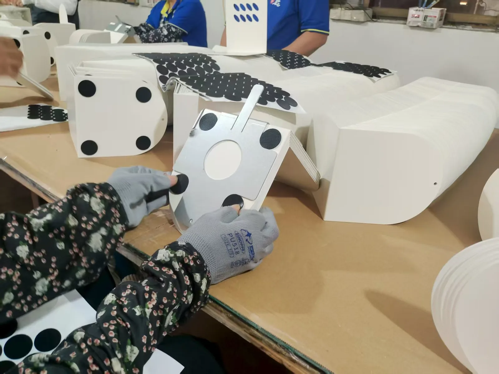
Principle 3: Design for Easy Handling
Design parts that are easy to pick up, orient, and position. Avoid: parts that tangle or nest, parts that are difficult to orient, parts that are too small or too thin to handle, parts with sharp edges. Use: symmetry to reduce orientation requirements, asymmetric features only where needed for orientation, generous chamfers and radii for easy insertion.
Principle 4: Design for Easy Insertion
Design parts that insert easily into their correct position. Use: chamfers and lead-ins for alignment, generous clearances where tolerances allow, locating features (pins, tabs, slots), self-locating features that guide the part into position.
Principle 5: Design for Easy Fastening
Minimize fastening operations and make them easy. Use: the minimum number of fasteners, standard fastener sizes, access for tools, fasteners that can be installed from one side, self-clinching fasteners for thin sheet metal, blind fasteners where access is limited.
Principle 6: Design for Symmetry
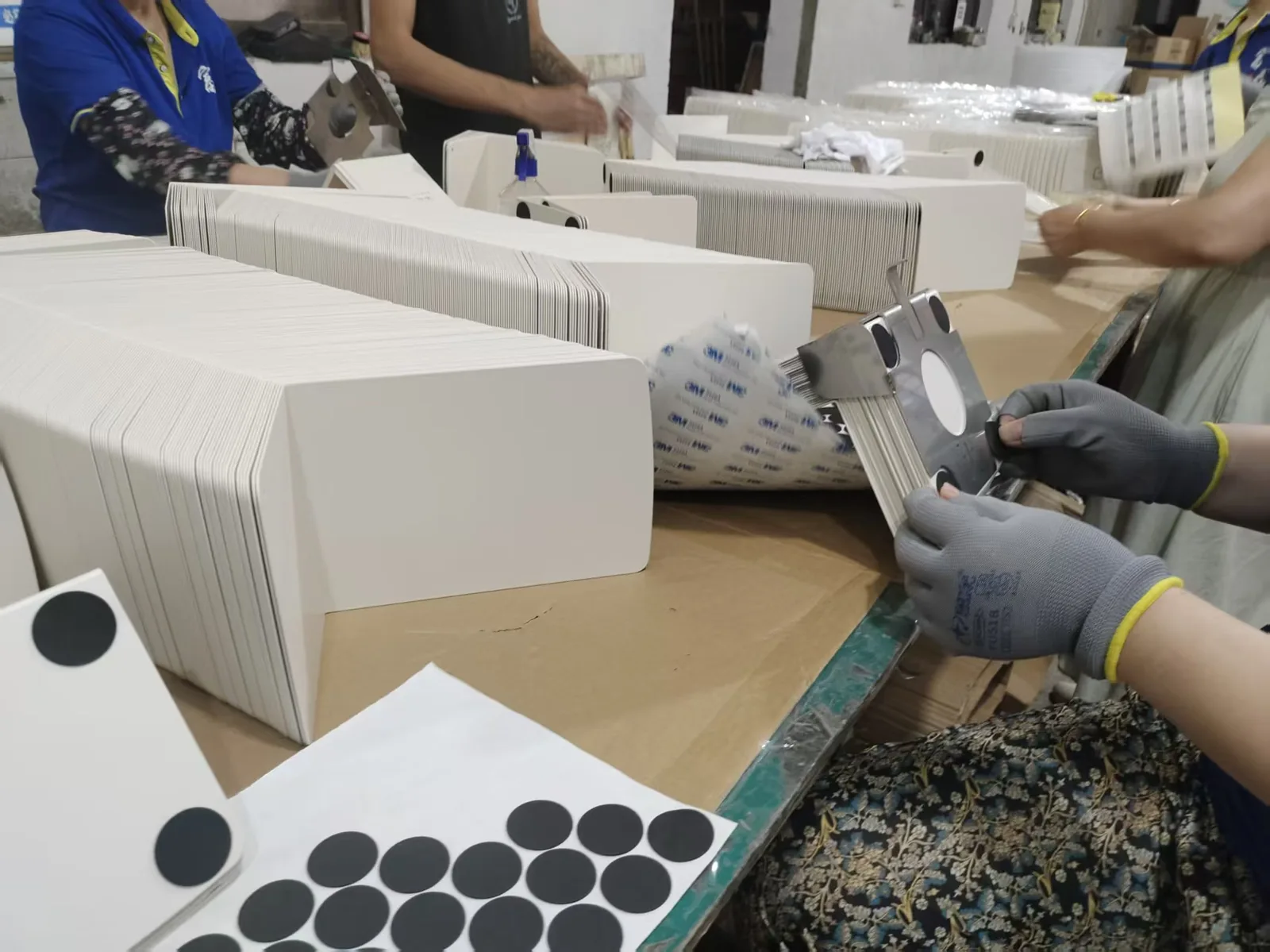
Symmetrical parts are easier to handle because orientation does not matter. Types of symmetry: rotational symmetry (part can be rotated), mirror symmetry (part can be flipped), full symmetry (any orientation works). When asymmetry is required, make it obvious to prevent incorrect orientation.
Principle 7: Design for Poka-Yoke
Design the product so that errors are impossible. Use: asymmetric hole patterns, locating features that only allow correct orientation, unique component sizes, color coding.
DFA Guidelines for Sheet Metal
Tab and Slot Design
Use tabs and slots for self-locating assembly. Tabs on one part insert into slots on another. Provides alignment without fixtures. Eliminates need for clamping during welding. Reduces assembly time and improves accuracy.
Self-Clinching Fasteners
Use self-clinching nuts and studs instead of: separate nuts and washers, welded nuts, tapped holes in thin material. Benefits: permanent, strong, flush installation, faster assembly.
Form Features for Alignment
Use sheet metal form features for alignment: lance and tab, shear form, emboss and mating hole. These features are formed during the manufacturing process at no additional cost. They provide alignment and positioning during assembly.
Minimal Fastener Variety
Use one fastener size throughout the product when possible. Reduces tool changes during assembly. Reduces inventory. Simplifies operator training. If multiple sizes are necessary, minimize the variety.
Access for Tools
Ensure that tools can access all fasteners. Consider: wrench swing, screwdriver access, drill access for rivets, socket access for bolts. Avoid: tight spaces, blind holes, fasteners behind obstructions. Design access holes or cutouts where needed.
Avoid Trapped Areas
Design so that: operators can reach all assembly points, tools can access all fasteners, inspection can be performed, cleaning is possible. Avoid creating enclosed spaces that cannot be accessed.
Welding Considerations
Design for minimal welding: use mechanical fastening where possible. Design for welding access: ensure welding gun can reach weld joints. Minimize weld length: use intermittent welds. Design for welding sequence: consider distortion. Design for welding fixtures: provide locating features.
Coating Considerations
Consider coating in the design: avoid areas where coating cannot reach, design drainage for coated parts, avoid contact points that may be damaged by coating, consider coating thickness on fit-up dimensions. Design for touch-up of welded areas.
DFA Analysis Process
Step 1: Analyze Current Design
List all parts in the assembly. Identify part function. Determine if each part is necessary. Count fasteners. Estimate assembly time for each part. Identify handling and insertion difficulties.
Step 2: Identify Improvement Opportunities
Can parts be combined? Can fasteners be eliminated? Can handling be simplified? Can insertion be made easier? Can symmetry be improved? Can error-proofing be added?
Step 3: Redesign
Apply DFA principles to redesign. Create alternative designs. Evaluate trade-offs. Select the best design. Document the rationale.
Step 4: Estimate Savings
Calculate assembly time reduction. Calculate cost reduction. Calculate inventory reduction. Calculate quality improvement. Compare to implementation cost. Determine return on investment.
Step 5: Implement and Monitor
Implement the improved design. Monitor assembly performance. Measure actual savings. Identify further improvement opportunities. Document for future application.
DFA Metrics
Part Count
Total number of parts in the assembly. Lower is better. Track part count reduction over time. Target: minimize while maintaining function.
Assembly Time
Total time to assemble the product. Lower is better. Measured through time study. Compare before and after DFA implementation.

Assembly Cost
Total cost of assembly operations including labor and equipment. Lower is better. Calculate savings from DFA improvements.
Assembly Efficiency
Assembly efficiency = theoretical minimum assembly time / actual assembly time. Higher is better. Theoretical minimum assumes ideal design with minimum parts and operations. Typical products: 5-30% efficiency. Target: improve efficiency through DFA.
Common DFA Mistakes
Over-Consolidation
Combining too many functions into one part can make the part: difficult to manufacture, expensive to produce, difficult to inspect, impossible to service. Balance part reduction with manufacturability.
Ignoring Service
Products designed only for assembly may be difficult to disassemble for service. Consider: access for maintenance, fastener removability, component replacement, disassembly sequence.
Not Considering Manufacturing
A design that is easy to assemble but difficult to manufacture is not optimal. Consider both DFA and DFM together. Balance assembly efficiency with manufacturing efficiency.
At Fulei Metal
We support DFA through: design review for assembly efficiency. Recommendations for part reduction and standardization. Self-clinching fastener integration. Tab and slot design recommendations. Prototype assembly to verify design. Assembly time analysis and optimization. We help clients design products that are efficient to manufacture and assemble.
Conclusion
Design for Assembly is a powerful methodology for reducing assembly cost and improving quality. At Fulei Metal, our DFA expertise helps clients create sheet metal products that are efficient to assemble, high in quality, and cost-competitive.
If you are sourcing this type of part, our sheet metal assembly service page covers the tolerances, batch sizes and inspection we work to, and custom sheet metal fabrication shows the wider range we produce in Ningbo, China. For background reading before you request a quote, see Modular Design Principles for Sheet Metal Assembly.
The Assembly Decisions That Actually Drive Cost
DFA is not a checklist of part reductions. On sheet metal assemblies the cost sits in a small number of decisions made at drawing stage, and each one is cheap to change before tooling and expensive after.
The reference values below are the working range we hold on this process. They are starting points for a drawing review, not a substitute for checking the actual part.
| Assembly decision | What it costs when it is wrong | Change that removes the cost |
|---|---|---|
| Number of fasteners per joint | Every extra screw is assembly time, a separate part number and a chance to leave one out or fit the wrong one | Replace with self-clinching hardware, captive fasteners or a formed interlock where the joint is permanent |
| Whether the part can be located one way only | A symmetrical part can be fitted upside down or back to front, and the mistake is usually found by the customer | Break the symmetry — offset a hole, notch one flange, or make the mounting pattern directional |
| Tool access at the fastener | An assembler who cannot reach a screw with a driver adds time, cross-threads, or leaves the fastener loose | Leave driver swing clearance on the drawing, and check the access with the mating part, not in isolation |
| Part count in the sub-assembly | Each extra part adds a tolerance to the stack-up, a line item to the BOM and a handling step | Merge parts where the interface is permanent and where nothing downstream needs to be adjusted |
| Where the datum sits | Assembled dimensions drift and the assembler compensates by hand, so the assembly is only as good as the operator | Define the assembly datum on the drawing and carry it through to the fixture and the inspection plan |
| Direction the enclosure opens | Doors and panels that open against the service direction force the equipment to be moved before it can be worked on | Decide the service direction first and orient hinges, cable entry and clearance around it |
None of these need exotic tooling or a design restart. They need the datum, the orientation and the fastener access decided before the drawing is frozen — which is exactly what a DFM review is for.
Frequently Asked Questions
How is DFA different from DFM?
DFM asks whether a single part can be made repeatably at the quoted cost. DFA asks whether the finished assembly goes together without extra labour, fixtures or rework. A part can pass DFM and still fail DFA — a bracket that is easy to form but impossible to hold while its four screws are driven is the classic case.
We do not know the assembly tolerance yet. Can we still start?
Yes, but say so. We set the sheet metal detail tolerances to a general class and flag the dimensions that will need tightening once the stack-up is known. Tightening everything by default is the expensive answer: it adds inspection time to every part without improving how the assembly behaves.
When is merging parts the wrong move?
When it destroys the ability to adjust. Two bolted brackets let the assembler shim and align; one welded bracket does not. Merge where the joint is a permanent interface, keep it where something downstream still has to be positioned.
Questions about a specific part are usually faster to answer against the drawing — send it through the route below.
Related at Fulei Metal: sheet metal enclosure assembly service · assembly line balancing techniques · sheet metal bending service · custom sheet metal fabrication