
Discover the essential measurement tools for sheet metal inspection. Learn about calipers, micrometers, gauges, CMM, and proper usage for accurate results.
Introduction
Accurate measurement is the foundation of quality inspection. The right measurement tools, properly used and calibrated, ensure that sheet metal parts meet specifications. At Fulei Metal, we invest in quality measurement tools and train our inspectors in their proper use.
Overview of Measurement Tools
Tool Selection Criteria
Accuracy: tool must be more accurate than the tolerance being measured. General rule: tool accuracy 10x better than tolerance (10:1 rule) or at least 4:1 for less critical applications. Resolution: smallest increment the tool can display. Range: must cover the dimensions being measured. Type: contact vs. non-contact. Environment: temperature, cleanliness, accessibility.
Tool Categories
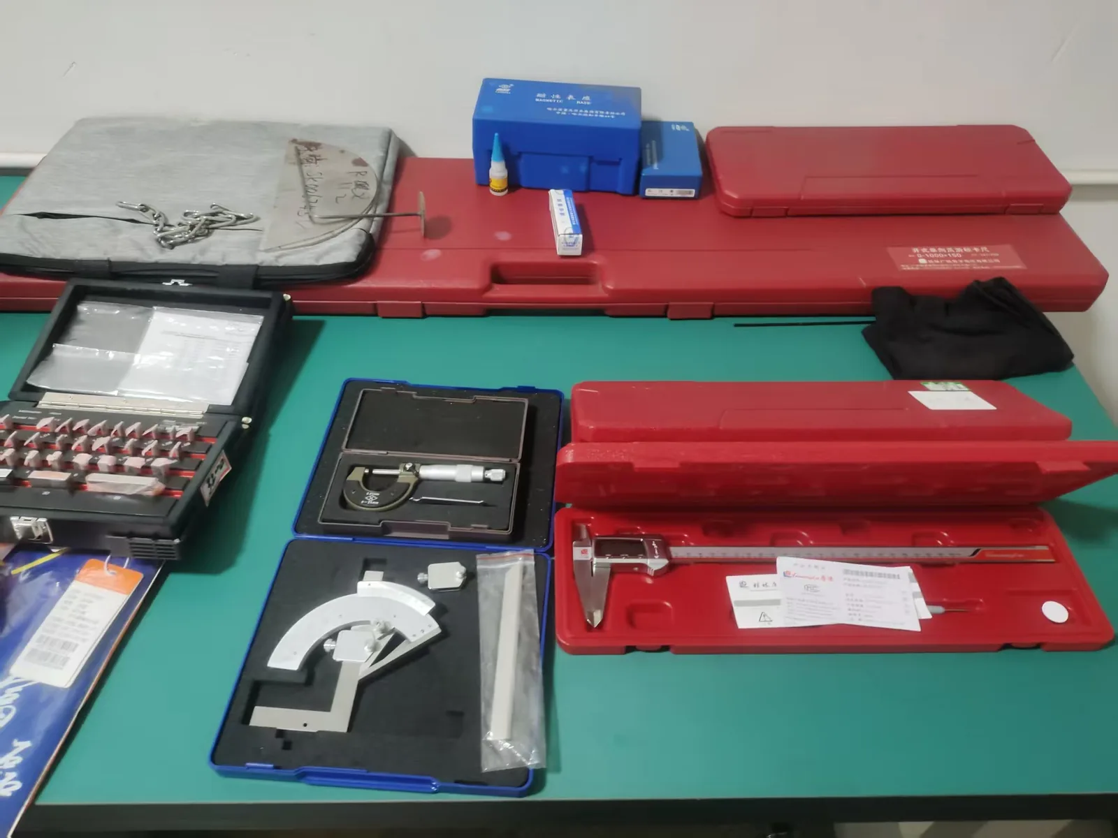
Hand tools: calipers, micrometers, rules, gauges. Bench tools: height gauges, surface plates, comparator. Advanced tools: CMM, vision systems, 3D scanners. Specialized tools: weld gauges, radius gauges, thread gauges.
Calipers
Types of Calipers
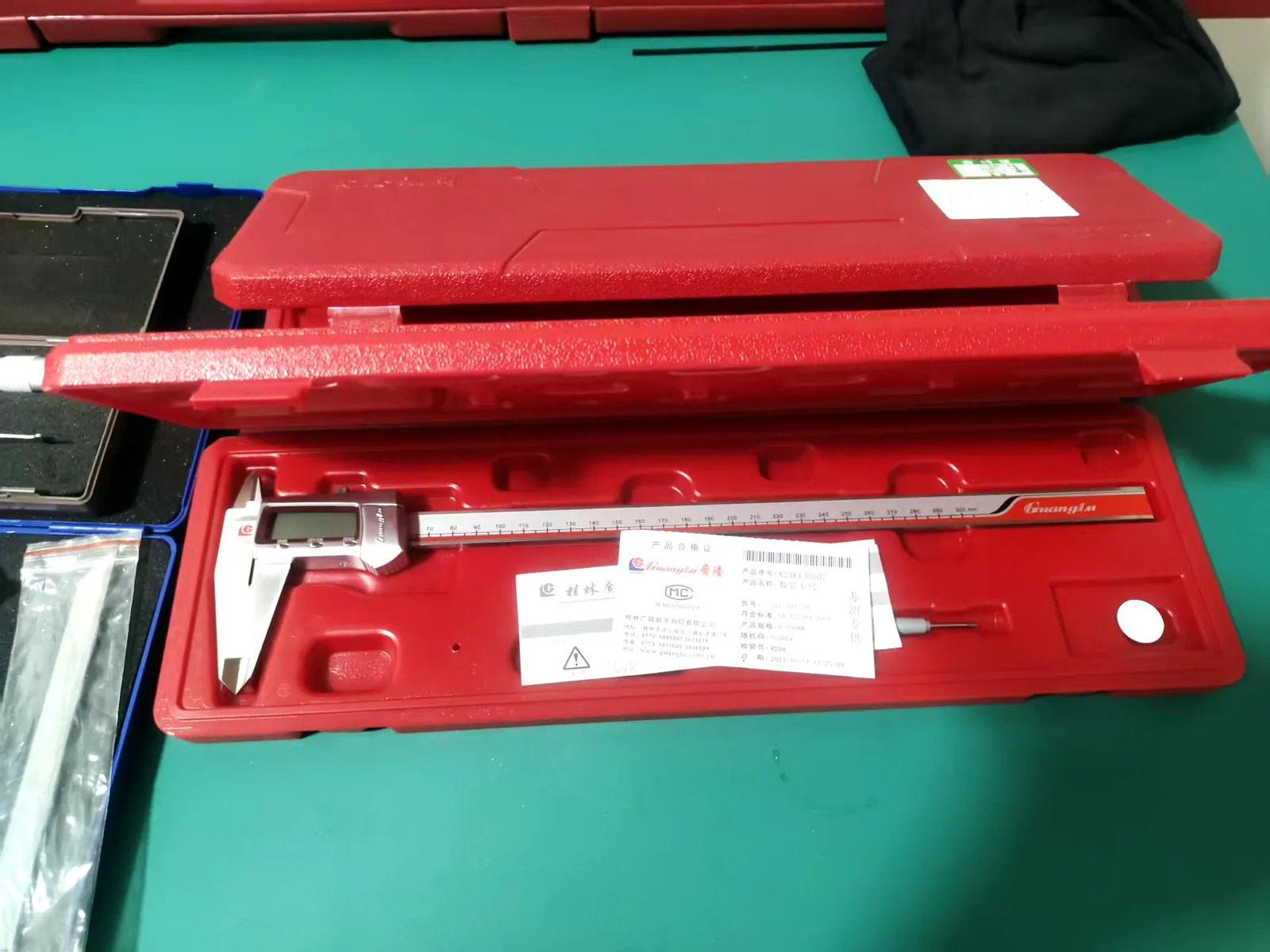
Digital caliper: digital display, easy reading, high resolution (0.01mm), data output capability. Most common in modern inspection. Dial caliper: mechanical dial display, resolution 0.02mm, no battery needed. Vernier caliper: scale reading, resolution 0.02mm or 0.05mm, requires skill to read, lowest cost.
Caliper Measurements
Outside measurement: measure outer dimensions of parts. Inside measurement: measure inner dimensions of holes and slots. Depth measurement: measure depth of holes, slots, and steps. Step measurement: measure height difference between surfaces.
Caliper Usage
Clean measuring faces before use. Check zero: close jaws and verify zero reading. Measure perpendicular to surface: avoid angular measurement error. Apply consistent force: excessive force causes error. Read at correct angle: avoid parallax error on dial and vernier. Maintain tool: keep clean, lubricated, and calibrated.
Caliper Accuracy
Digital: plus or minus 0.02mm for 150mm range. Dial: plus or minus 0.02mm for 150mm range. Vernier: plus or minus 0.02-0.05mm depending on quality. Accuracy decreases with larger ranges. Suitable for: general-purpose measurement, tolerances of 0.1mm or larger.
Micrometers
Types of Micrometers
Outside micrometer: measure outer dimensions. Inside micrometer: measure inner dimensions. Depth micrometer: measure depth. Digital micrometer: digital display, easy reading, data output. Mechanical micrometer: barrel and thimble reading.
Micrometer Ranges
Available in 25mm ranges: 0-25mm, 25-50mm, 50-75mm, etc. Each range requires its own micrometer. Interchangeable anvil micrometers: cover multiple ranges with one frame.
Micrometer Resolution and Accuracy
Resolution: 0.01mm for standard, 0.001mm for digital with high resolution. Accuracy: plus or minus 0.001-0.004mm depending on quality. Suitable for: precise measurement, tolerances of 0.01mm or larger.
Micrometer Usage
Clean anvil and spindle faces. Check zero: close on zero or use standard rod. Use ratchet stop or friction thimble: consistent measuring force. Measure perpendicular to surface. Temperature: allow tool and part to stabilize at same temperature. Read correctly: barrel scale plus thimble scale.
Height Gauges
Types of Height Gauges
Digital height gauge: digital display, high resolution, data output. Dial height gauge: mechanical dial display. Vernier height gauge: scale reading.
Height Gauge Usage
Mount on surface plate: flat, precision surface. Use as reference: surface plate is the datum. Measure height: from surface plate to feature. Measure depth: using depth attachment. Measure step: difference between two heights. Use with dial test indicator: for precise feature location.
Height Gauge Accuracy
Digital: plus or minus 0.02-0.05mm depending on range. Accuracy depends on surface plate quality. Suitable for: measuring vertical dimensions, flatness, parallelism.
Surface Plates
Purpose
Surface plate provides a flat reference surface for measurement. It is the datum for height measurement. It supports parts and measurement tools.
Materials
Granite: most common, stable, hard wearing. Available in various grades: 0 (highest), 1, 2, 3. Cast iron: traditional, can rust. Glass: for light-duty applications.
Surface Plate Care
Keep clean: dust and dirt affect measurement. Use surface plate cover when not in use. Do not drop tools on plate. Re-calibrate periodically: verify flatness. Support correctly: on three-point support.
Gauges
Pin Gauges
Precision pins for measuring hole diameters. Go/no-go: two pins, go pin (minimum), no-go pin (maximum). Available in sets: various diameters. Accuracy: plus or minus 0.001mm. Simple, fast hole inspection.
Radius Gauges
Metal templates with various radii. Check bend radii and corner radii. Match radius to template. Quick and simple. Limited accuracy.
Thread Gauges
Go/no-go thread gauges. Verify thread dimensions and quality. Plug gauges: for internal threads. Ring gauges: for external threads. Thread pitch gauges: verify thread pitch.
Feeler Gauges
Thin metal strips of known thickness. Measure gaps and clearances. Available in sets: 0.02-1.0mm. Accuracy: plus or minus 0.005mm. Useful for: bend angle inspection, gap measurement.
Weld Gauges
Measure weld dimensions. Fillet weld gauge: measure leg length and throat. Bridge cam gauge: measure multiple weld dimensions. Weld profile gauge: check weld profile. Essential for weld inspection.
Angle Gauges
Universal bevel protractor: measure angles. Accuracy: 5 arc minutes. Digital angle gauge: electronic display. Square: verify 90-degree angles. Adjustable angle gauge: set and check specific angles.
Coordinate Measuring Machine (CMM)
What is a CMM?
CMM measures 3D coordinates of points on a part surface. It provides precise measurement of complex geometries. It can measure: dimensions, positions, profiles, geometric tolerances.
CMM Types
Bridge type: most common, high accuracy. Cantilever type: open access. Horizontal arm: for large parts. Portable: articulated arm, flexible. Non-contact: optical or laser.
CMM Probes
Touch-trigger probe: contacts surface at discrete points. Scanning probe: continuously measures surface. Optical probe: non-contact measurement. Stylus selection: ball size and shape, extension length.
CMM Capabilities
3D coordinate measurement. Complex geometry verification. CAD model comparison. Statistical analysis. Automated measurement routines. Reverse engineering.
CMM Operation
Mount part on CMM table. Align part to coordinate system. Probe features to be measured. Software analyzes data. Generate inspection report. Requires trained operator.
Vision Measurement Systems
Optical Comparator
Projects part profile on screen. Compare to overlay template. Measure angles and dimensions. Suitable for: small parts, profile inspection.
Video Measurement System
Camera-based measurement. Measures features on screen. Non-contact: suitable for delicate parts. Automated measurement: programmable. High accuracy for small features.
Measurement Environment
Temperature
Standard temperature: 20°C. Temperature variation causes thermal expansion. Allow parts and tools to stabilize. Consider material expansion coefficient. Critical measurements: temperature-controlled room.
Cleanliness
Dust and dirt affect measurement. Clean parts before measurement. Clean measuring tools regularly. Keep measurement area clean.
Vibration
Vibration affects precision measurement. Isolate measurement equipment from vibration. Use vibration-damping tables. Avoid measuring near vibrating equipment.
Calibration
Why Calibrate?
Calibration verifies tool accuracy. It ensures measurement traceability. It is required by quality systems. It provides confidence in measurement results.
Calibration Frequency
Based on: usage frequency, environment, manufacturer recommendation, quality system requirement. Typical: 6-12 months. More frequent for critical tools or harsh environments.
Calibration Standards
Traceable to national or international standards. Calibration laboratory accredited to ISO 17025. Calibration certificate documents results.
Calibration Records
Maintain calibration records for each tool. Include: tool ID, calibration date, next due date, results, standard used. Label tools with calibration status. Remove out-of-calibration tools from service.
At Fulei Metal
Our measurement tool inventory includes: digital calipers in various ranges. Micrometers for precision measurement. Digital height gauges. Granite surface plate. CMM for 3D measurement. Vision measurement system. Pin gauges, radius gauges, thread gauges, weld gauges, feeler gauges. All tools are calibrated and maintained. We ensure accurate measurement for quality inspection of all our products.
Conclusion
Quality measurement tools are essential for accurate inspection. At Fulei Metal, our investment in measurement tools, calibration, and operator training ensures that our dimensional inspection provides reliable results for our global clients.
Fulei Metal builds components like this in-house. The quality inspection service page explains how the process is set up and checked, while custom sheet metal fabrication covers the materials and finishes we normally run. Related reading: Outgoing Inspection.
Instrument Capability Against Feature Type
This is the working reference we use when deciding what an inspection plan should call for. It is organised by what you need to verify, because that is the question a drawing review actually has to answer.
| Instrument | Resolution | Best used for | Where it stops being useful |
|---|---|---|---|
| Steel rule / tape measure | 0.5 mm | Rough overall size, layout reference, checking a part is the right one | Anything with a drawing tolerance on it |
| Vernier or digital calliper | 0.01–0.02 mm | Outside and inside dimensions, hole diameters, step heights | Deep features the jaws cannot reach squarely; soft or burred edges |
| Outside micrometer | 0.001 mm | Sheet thickness, small solid features | Thin sheet without a consistent closing force; hot parts straight off a process |
| Height gauge on a surface plate | 0.01 mm | Step heights, hole positions measured from a datum face | Parts that do not sit flat, and anything that needs a true 3D alignment |
| Plug / pin gauges | Go–no-go | Hole diameter against a limit, quick and operator-independent | Any hole you need a numerical reading from |
| Digital protractor / angle gauge | 0.1° | Bend angles on formed parts | Angles defined between faces the gauge cannot sit flat on |
| CMM | 0.001–0.01 mm | Complex geometry, position relative to a datum, first article coverage | Features it cannot reach, and parts whose support condition changes their shape |
Every instrument here is only as good as its calibration status and the setup it is used in. A 0.001 mm micrometer held at the wrong angle to a burred edge reads worse than a calliper held properly.
Frequently Asked Questions
What does the “4:1 gauge ratio” mean in practice?
It means the instrument should resolve about four times finer than the tolerance it checks. To verify a ±0.10 mm dimension you want an instrument good to about 0.025 mm — which rules out a steel rule and points at a calliper or micrometer. Applying the ratio keeps measurement uncertainty from consuming the tolerance band you paid for.
Do you calibrate your measuring instruments?
Yes, on a schedule against traceable reference standards, and calibration records are available during a customer or third-party audit. Instruments out of calibration are withdrawn from the inspection area rather than left in circulation with a note attached.
My drawing calls a general tolerance of ±0.2 mm. Do I need a CMM?
No — a CMM on general tolerances adds cost and lead time and tells you nothing extra. CMM time is worth spending on the features your drawing controls tightly, on geometry hand tools cannot reach, and on first article work where you need the whole part rather than a sample of it.
Questions about a specific part are usually faster to answer against the drawing — send it through the route below.
Related at Fulei Metal: sheet metal quality inspection service · CMM measuring guide