
Welding knowledge for enclosure buyers
TIG Welding Sheet Metal: An OEM Enclosure Guide
TIG welding can be a good choice for thin stainless steel, aluminum and visible enclosure joints when control and appearance matter. It is not automatically the best or lowest-cost process for every seam; material, access, production volume, distortion risk and finishing expectations should decide the route.
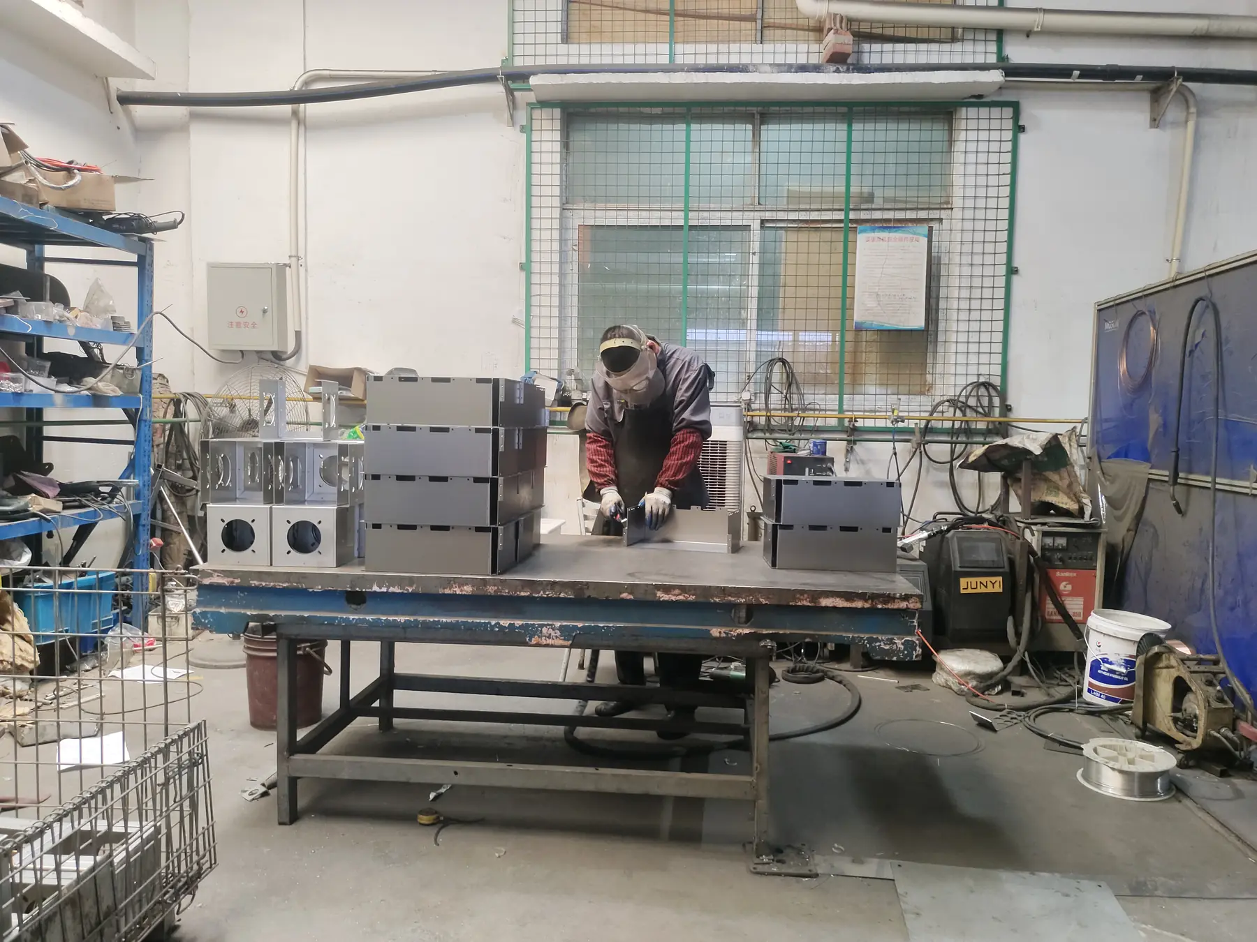
Buyer summary
What to Decide Before Requesting a Quote
| Best-fit questions | Material, thickness, joint access, cosmetic face and annual quantity |
|---|---|
| Drawing information | Weld location, symbol, required appearance and critical post-weld geometry |
| Main production risks | Fit-up variation, burn-through, heat distortion and excess grinding |
| Inspection focus | Joint continuity, visible defects and drawing-defined dimensions |
When TIG Welding Fits a Sheet Metal Enclosure
TIG welding gives the operator close control of the arc and filler addition. That can be useful around thin stainless panels, aluminum assemblies, corners and joints that remain visible after fabrication.
For repeat OEM work, however, the decision should also consider cycle time and fixture stability. A long cosmetic seam on a thin door may look straightforward in CAD but accumulate heat and pull the panel out of flatness. In some designs, a shorter weld pattern, additional formed features or mechanical fastening produces a more stable result.
The Drawing Must Define More Than “TIG Weld”
A useful fabrication drawing identifies the joint location, weld length or continuity, accessible side, visible face, grinding scope and the geometry that must remain controlled after welding. If penetration or a specific weld standard matters, the buyer should state the applicable requirement and evidence.
Gaps caused by inconsistent laser cutting or bending cannot be repaired economically by adding more weld. Fit-up, tack sequence and fixture contact are part of the welding process, so the factory needs the assembly drawing as well as individual part drawings.
How We Reduce Distortion and Cosmetic Risk
The practical controls are joint fit-up, restraint, tack order, balanced sequence, limited heat input and checking the assembly while correction is still possible. Grinding should be limited to the faces that truly require it because excessive dressing can thin the sheet and create waves.
For a prototype, the first article should verify squareness, door fit, mounting interfaces and the final appearance after cleaning or coating. Once those points are approved, the same fixture, sequence and revision become the basis for the repeat batch.
Buyer questions
Questions Procurement and Engineering Teams Usually Ask
These answers define the discussion points. Final values and acceptance criteria are confirmed against the project drawing and purchase requirements.
Is TIG always the best process for thin sheet metal?
No. Joint access, appearance, material, thickness, heat sensitivity and production volume determine whether TIG or another joining route is more practical.
What should a drawing say about visible welds?
Identify cosmetic faces, weld locations, grinding scope and the approved appearance reference. A general note such as "smooth weld" is not an objective acceptance standard.
How is distortion evaluated?
We review the completed assembly against agreed datums, flatness, squareness, door gaps and mating dimensions rather than judging the weld bead alone.
RFQ checklist
Information That Makes the Technical Reply Useful
- Send material grade and actual thickness
- Mark visible and non-visible welds
- Define continuous, intermittent or sealed joints
- Identify post-weld flatness and squareness needs
- State finish, grinding and inspection expectations
Tungsten, Current and Gas Settings That Hold on Thin Sheet
TIG is chosen for sheet metal when the weld is visible, when the joint has to be leak-tight, or when the heat-affected zone has to stay narrow. The values below are the starting window our welders tune from on a sample coupon before production. They are not finished procedure values: polarity, tungsten grind, backing and joint fit-up each move them.
| Material and thickness | Tungsten | Polarity / current | Filler wire | Argon flow (L/min) |
|---|---|---|---|---|
| Carbon steel 0.8-1.5 mm | Lanthanated 1.6 mm | DCEN 35-70 A | ER70S-2 or ER70S-6, 0.8-1.0 mm | 6-8 |
| Carbon steel 2.0-3.0 mm | Lanthanated 2.4 mm | DCEN 80-130 A | ER70S-6, 1.6 mm | 8-10 |
| Stainless 304/316 0.8-1.5 mm | Lanthanated or ceriated 1.6 mm | DCEN 30-65 A | ER308L or ER316L, 0.8-1.0 mm | 6-8, plus back purge on roots |
| Stainless 304/316 2.0-3.0 mm | Lanthanated 2.4 mm | DCEN 75-120 A | ER308L or ER316L, 1.6 mm | 8-10, plus back purge |
| Aluminium 1.0-2.0 mm | Zirconiated or lanthanated 2.4 mm | AC, balanced towards cleaning, 60-110 A | ER4043 or ER5356, 1.6 mm | 8-10 |
| Aluminium 3.0-4.0 mm | Zirconiated or lanthanated 3.2 mm | AC 110-170 A | ER5356 for strength, ER4043 for crack resistance, 2.4 mm | 10-14 |
Two disciplines carry more weight than any number in that table. Keep the tungsten grind consistent, because a blunt or contaminated tip wanders and widens the bead beyond what the current setting predicts. And keep the gas shield intact until the bead has cooled below the point where it oxidises — post-flow is not optional on stainless. Both are the usual explanation for grey, sugared beads that fail a cosmetic inspection while every parameter on the sheet looks correct.
From research to RFQ
Apply the Guidance to Your Actual Drawing
Send the current files, quantity, material, finish and assembly context. We will identify the questions needed for a practical manufacturing review.