
Identify and prevent common defects in sheet metal manufacturing. Learn about defect types, root causes, detection methods, and corrective actions for each stage.
Introduction
Defects in sheet metal manufacturing can occur at any stage: cutting, bending, welding, surface treatment, and assembly. Understanding common defects, their causes, and prevention methods is essential for producing high-quality products. At Fulei Metal, our defect analysis and prevention program drives continuous quality improvement.
Defect Classification
By Severity
Critical defects: affect safety or core function. Must not reach customer. Examples: cracks, structural failures, missing safety features. Major defects: affect appearance or may reduce function. Examples: deep scratches, weld defects, coating failures. Minor defects: cosmetic, do not affect function. Examples: light scratches, minor color variation.
By Process
Cutting defects: burr, dross, rough edge, dimensional error. Bending defects: incorrect angle, springback, cracking, marking. Welding defects: porosity, cracks, undercut, distortion. Surface treatment defects: poor adhesion, orange peel, pinholes, color variation. Assembly defects: misalignment, missing components, loose fasteners.
Cutting Defects
Burr
Description: rough edge left on cut part. Causes: dull cutting tool, incorrect cutting parameters, worn nozzle (laser). Prevention: maintain sharp tools, optimize parameters, replace worn components. Detection: visual inspection, touch test. Correction: deburr with file, grinder, or tumbling.
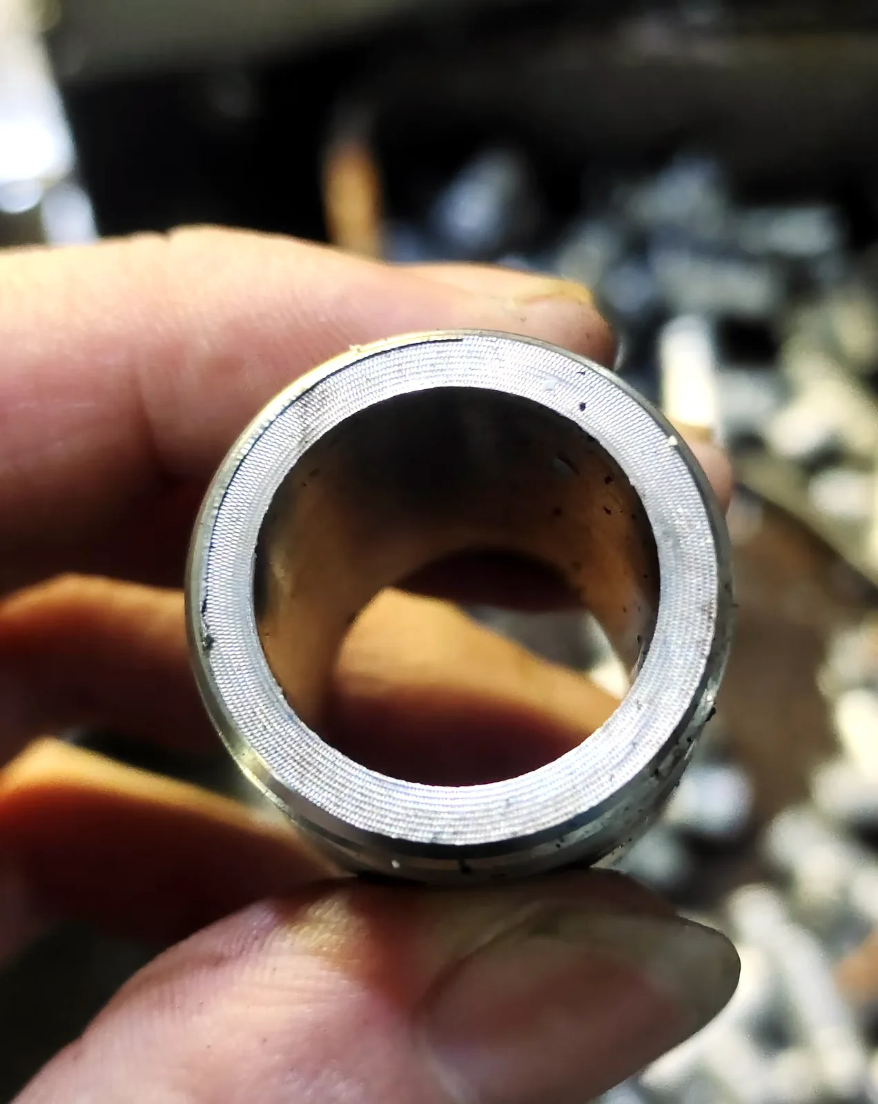
Dross
Description: oxidized metal deposit on bottom edge of laser cut. Causes: incorrect cutting speed, incorrect focus position, low gas pressure. Prevention: optimize cutting parameters, maintain focus position, ensure adequate gas pressure. Detection: visual inspection. Correction: remove dross with file or grinder.
Rough Cut Edge
Description: uneven or rough edge surface. Causes: worn nozzle, incorrect gas pressure, dirty optics, material variation. Prevention: regular maintenance, parameter optimization, material quality control. Detection: visual inspection, surface roughness measurement. Correction: secondary finishing operation.
Dimensional Error
Description: cut dimension outside tolerance. Causes: incorrect program, machine calibration, material movement, thermal expansion. Prevention: verify program, calibrate machine, secure material, control temperature. Detection: dimensional inspection. Correction: re-cut if possible, scrap if not.
Bending Defects
Incorrect Bend Angle
Description: bend angle not matching specification. Causes: incorrect tooling selection, wrong machine setting, springback not compensated, material variation. Prevention: correct tooling, proper setup, springback compensation, material control. Detection: angle measurement. Correction: re-bend if possible.
Springback
Description: material returns partially after bending, changing angle. Causes: material properties (high yield strength), bend radius, material thickness. Prevention: over-bend to compensate, use bottom bending, use laser adjusting. Detection: angle measurement after bending. Correction: re-bend with adjusted angle.
Cracking at Bend
Description: cracks form at bend radius during bending. Causes: bend radius too small for material, grain direction parallel to bend, hard material, insufficient bend allowance. Prevention: use larger bend radius, orient grain perpendicular to bend, anneal if needed, correct bend allowance. Detection: visual inspection, dye penetrant. Correction: scrap cracked parts, adjust process.
Surface Marking
Description: marks or indentation on bent surface. Causes: worn or damaged tooling, insufficient lubrication, material slippage. Prevention: maintain tooling, use proper lubrication, secure material. Detection: visual inspection. Correction: polish or rework if minor, scrap if severe.
Welding Defects
Porosity
Description: gas pockets in weld metal. Causes: contaminated surface, moist electrode, incorrect gas flow, dirty base metal. Prevention: clean surfaces, dry electrodes, correct gas flow, proper shielding. Detection: visual, radiographic, ultrasonic. Correction: grind out and re-weld.
Cracks
Description: fractures in weld or heat-affected zone. Causes: high residual stress, rapid cooling, hydrogen embrittlement, poor joint design. Prevention: preheat, control cooling, proper joint design, low hydrogen process. Detection: visual, dye penetrant, magnetic particle, radiographic. Correction: grind out completely and re-weld.
Undercut
Description: groove melted into base metal at weld toe. Causes: excessive current, incorrect travel speed, incorrect electrode angle. Prevention: correct parameters, proper technique. Detection: visual, weld gauge. Correction: grind and fill, or re-weld.
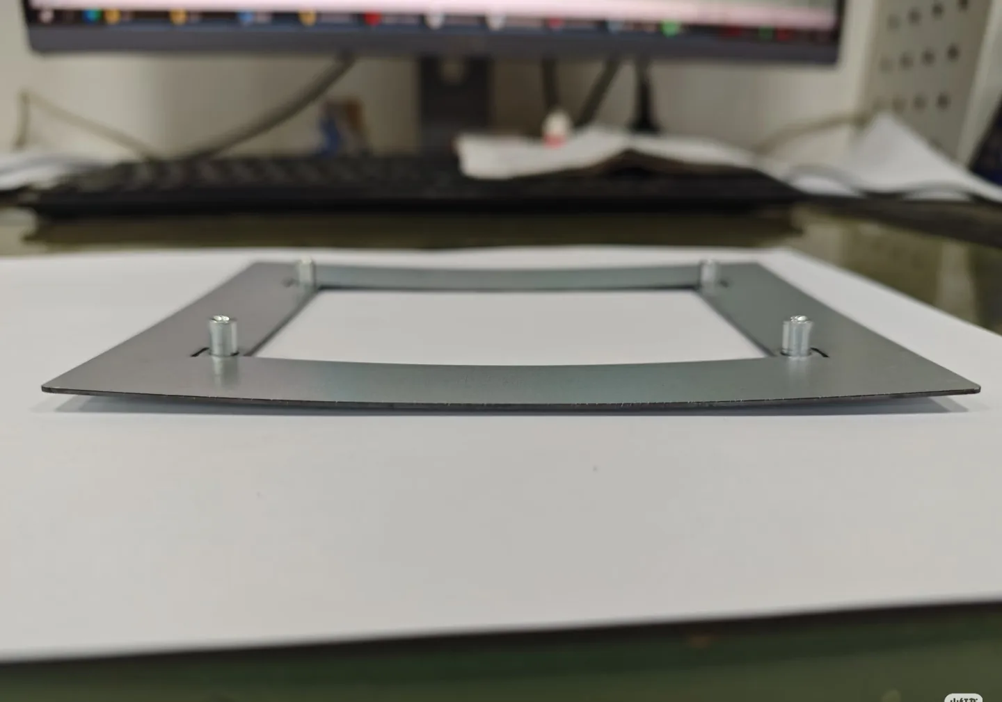
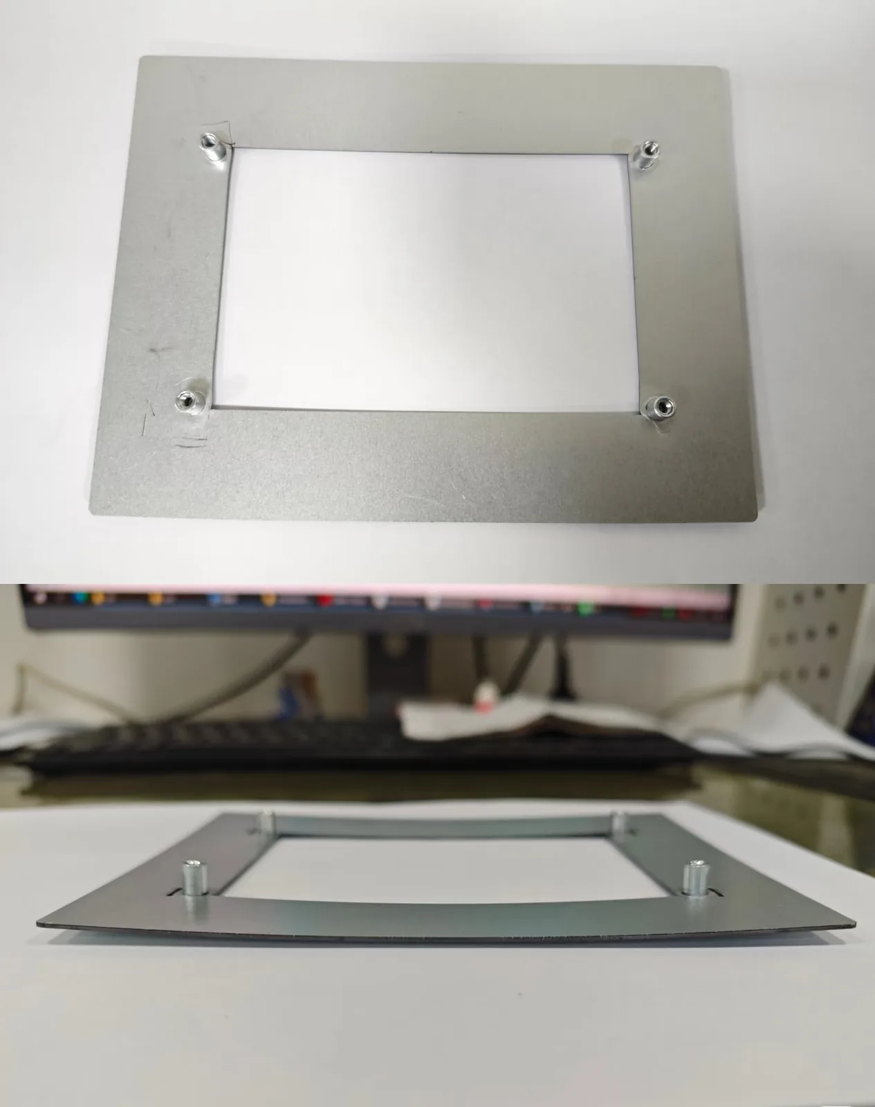
Distortion
Description: warping of part due to welding heat. Causes: excessive heat input, poor weld sequence, inadequate clamping. Prevention: optimize sequence, use clamping, minimize weld size, intermittent welds. Detection: dimensional inspection. Correction: straightening, stress relief.
Surface Treatment Defects
Poor Adhesion
Description: coating peels or flakes from surface. Causes: inadequate surface preparation, contamination, incorrect curing. Prevention: proper pre-treatment, thorough cleaning, correct curing parameters. Detection: cross-cut test, tape test. Correction: strip and re-coat.
Orange Peel
Description: uneven surface texture resembling orange peel. Causes: excessive coating thickness, incorrect curing temperature, powder particle size. Prevention: control film thickness, correct curing, proper powder selection. Detection: visual inspection. Correction: strip and re-coat.
Pinholes
Description: small holes through coating. Causes: trapped air or moisture, excessive thickness, contamination. Prevention: proper pre-treatment, control thickness, clean environment. Detection: visual inspection. Correction: strip and re-coat.
Color Variation
Description: uneven or incorrect color. Causes: coating thickness variation, curing temperature variation, batch variation. Prevention: consistent thickness, consistent curing, batch control. Detection: visual, colorimeter. Correction: re-coat if unacceptable.
Assembly Defects
Misalignment
Description: components not in correct relative position. Causes: fixture inaccuracy, component variation, welding distortion, incorrect assembly. Prevention: accurate fixtures, component control, distortion control, proper assembly sequence. Detection: dimensional inspection, visual. Correction: disassemble and re-assemble, or adjust.
Missing Components
Description: required component not installed. Causes: incomplete kit, operator oversight, unclear instructions. Prevention: kitting with verification, checklists, error-proofing. Detection: visual inspection, functional test. Correction: install missing component.
Loose Fasteners
Description: fasteners not properly tightened. Causes: insufficient torque, missing locking feature, vibration. Prevention: calibrated torque tools, locking fasteners, thread locker. Detection: torque audit, visual. Correction: re-torque or replace fastener.
Surface Damage
Description: scratches or dents from assembly handling. Causes: rough handling, tool contact, inadequate protection. Prevention: careful handling, protective film, non-marring tools. Detection: visual inspection. Correction: rework or re-coat if severe.
Defect Analysis Process
Step 1: Identify the Defect
Describe: what the defect is, where it occurs, when it occurs, how often it occurs. Collect: photos, samples, measurements. Document the defect clearly.
Step 2: Determine Root Cause
Use 5 Whys: ask “why” until root cause found. Use fishbone diagram: consider man, machine, material, method, measurement, environment. Verify root cause with data. Distinguish between root cause and symptom.
Step 3: Develop Corrective Action
Address root cause, not symptom. Consider: feasibility, cost, effectiveness, side effects. Select best corrective action. Plan implementation.
Step 4: Implement and Verify
Implement corrective action. Monitor results. Verify defect is eliminated. Verify no new problems introduced. Document effectiveness.
Step 5: Standardize
Update procedures to prevent recurrence. Train operators on new procedure. Update inspection to catch recurrence. Monitor long-term effectiveness.
Defect Prevention Strategies
Process Control
SPC for critical parameters. Regular calibration. Equipment maintenance. Parameter monitoring. Process capability analysis.
Error-Proofing (Poka-Yoke)
Design fixtures that prevent incorrect assembly. Use sensors to verify operations. Implement interlocks. Color-code components. Use barcode verification.
Training
Operator training on defect recognition. Process training on correct methods. Quality awareness training. Cross-training for flexibility. Regular retraining.
Design for Quality
Design parts that are easy to manufacture correctly. Avoid features that are prone to defects. Specify achievable tolerances. Consider manufacturing capabilities in design.
Defect Tracking and Analysis
Defect Database
Record all defects: type, location, frequency, root cause, corrective action. Track trends over time. Identify recurring problems. Prioritize improvement efforts.
Pareto Analysis
80% of defects from 20% of causes. Focus on most frequent defects. Prioritize by frequency and severity. Target high-impact improvements first.
Defect Rate Tracking
Track defect rate over time. Monitor effectiveness of improvements. Set targets for defect reduction. Celebrate improvements.
At Fulei Metal
Our defect management program includes: defect classification system. Root cause analysis for all significant defects. Corrective and preventive action (CAPA) system. Defect tracking database. Pareto analysis for prioritization. Regular quality reviews. Continuous improvement program. Operator training on defect prevention. We systematically identify, analyze, and prevent defects to continuously improve our quality for our global clients.
Where Each Defect Is Cheapest to Catch
Defects are usually grouped by process, which is how the shop sees them. Grouping them by the point at which they are cheapest to catch is a better guide to where the effort belongs.
Almost every row below shares one cause: a parameter that was never recorded on the day it was correct, so it drifted without anyone noticing it move.
| Defect | Usual root cause | Cheapest detection point | Countermeasure that removes it |
|---|---|---|---|
| Burr on a cut edge | Worn or blunt tooling, incorrect clearance, wrong focus or nozzle condition on the laser | First-off, at the machine | Change the consumable on a count rather than on appearance, and record the count |
| Dross on a laser-cut edge | Assist gas pressure or focus off for the thickness, cutting speed too low | At the machine, during the first-off | Dial the parameters in per material and thickness, then record that setting as the baseline for the job |
| Dimensional error after bending | Wrong bend deduction, backgauge error, or a material batch thinner than nominal | First-off, then at the in-process interval | Confirm the deduction against the actual material batch instead of the nominal thickness |
| Bend angle out, or springback | Material batch variation, and no compensation set for it | First-off, on a trial bend | Set the angle by measured trial on the batch in hand, not by the setting that worked last time |
| Porosity or incomplete fusion in a weld | Contaminated surface, wrong gas flow, wrong parameters, or an uncontrolled joint gap | At the welding check, and by NDT where the joint is critical | Clean before welding, set and hold the gap, and qualify the welder for the position being welded |
| Distortion after welding | Heat input, welding sequence, and no restraint while cooling | After welding – sometimes only after finishing | Balance the sequence and use a fixture, and allow for straightening in the route instead of hoping |
| Coating colour or thickness off spec | Pre-treatment, bath chemistry, or film build outside the window | At the coating line, per batch | Control and record the line parameters per batch so a drift is visible as a number |
| Hardware wrong or missing | No kit discipline, and look-alike fasteners stored together | At assembly and again at outgoing release | Kit per unit against the BOM, and make the check physical rather than assumed |
| Scratches and transit damage | Packing method that does not match the route, and no record of how it was packed | At the customer – which is already too late | Pack against the actual route, and photograph the packed pallet before it closes |
Two of these rows are worth more attention than the rest. Distortion and transit damage both get found late, and both are the ones where a decision made at drawing or packing stage would have removed the problem entirely. The process-by-process breakdown is in sheet metal defect analysis, with the forming-specific detail in bending defects and the welding detail in welding defect prevention.
Frequently Asked Questions
Which defects can actually be reworked?
Burrs can be removed, mild distortion can sometimes be straightened, and a coating can be stripped and redone. A bend that has been pushed past what the material takes, or a weld that has cracked, cannot be returned to new condition – it can only be replaced. Sorting reworkable from non-reworkable defects at the point of discovery is what decides whether a lot is salvageable.
How do we agree what counts as a cosmetic defect?
Against a written standard and a physical reference, agreed before production rather than after the first argument. Colour, sheen, a permissible scratch length on a non-visible face and the treatment of edges are all legitimately negotiable – what is not workable is deciding them by opinion once parts exist. Appearance is also the defect class least likely to be caught by a sample inspection.
Why not publish photographs of your own defects?
Because defective parts, lot records and the reasons behind them belong to the customer and to the traceable record, not to a marketing page. What we can do is review defects with you against your own drawing and acceptance standard, which is more useful anyway – a generic defect photo rarely matches the characteristics that matter on a specific part.
Questions about a specific part are usually faster to answer against the drawing — send it through the route below.
Conclusion
Understanding and preventing defects is fundamental to quality manufacturing. At Fulei Metal, our comprehensive defect analysis and prevention program enables us to identify root causes, implement effective corrective actions, and continuously improve our processes, delivering ever-higher quality to our international clients.
Fulei Metal builds components like this in-house. The DFM engineering review page explains how the process is set up and checked, while custom sheet metal fabrication covers the materials and finishes we normally run. Related reading: assembly common problems solutions.
Related at Fulei Metal: custom sheet metal fabrication · common bending defects and solutions · welding defect prevention · quality inspection service