
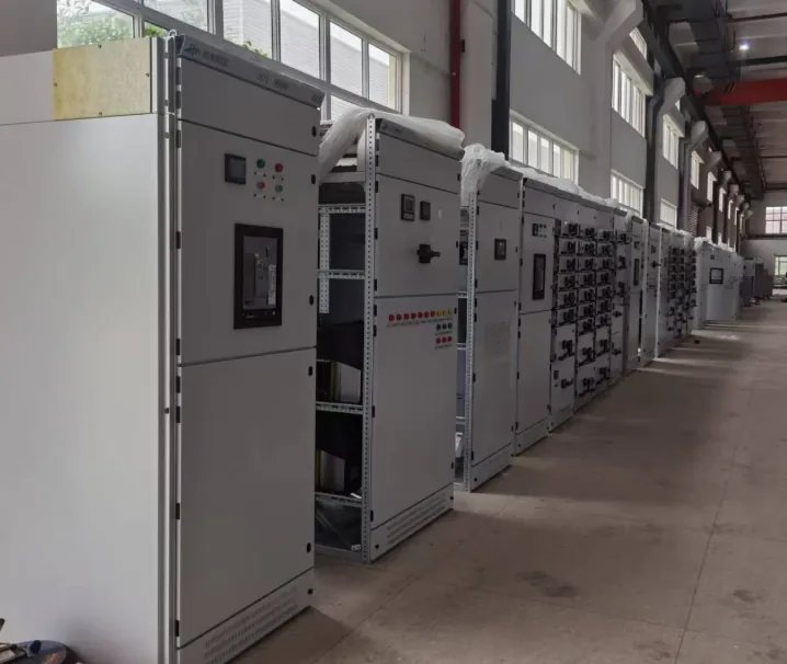
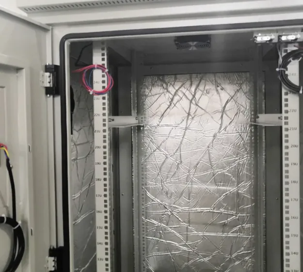
Industrial Automation Enclosures: Sheet Metal Cabinets for Control Systems
SKU: FL-IN-021
Sheet metal enclosures built around your automation layout — PLC and drive cabinets, HMI stations and machine-mounted control boxes, from one-off prototypes to whole line builds.
| Material | Cold-rolled steel (SPCC 1.5-2.0mm), galvanised steel, SUS304 / SUS316L, 5052 aluminium |
|---|---|
| Manufacturing Process | Laser cutting + CNC bending + welding + powder coating |
| Surface Finish | Powder coating (RAL 7035 / 7032 / 9005, or to sample) |
| Sheet Thickness | 1.0-3.0mm; internal frame members up to 4.0mm |
| Tolerance | ±0.3mm on cut and formed features |
| Dimensions | Custom. Typical floor-standing 600×800×2000mm; wall or machine mounted from 300×400×150mm |
| IP rating | IP54 as standard; IP65 with gasketed doors and sealed apertures |
| Doors | Single or double, with or without viewing window |
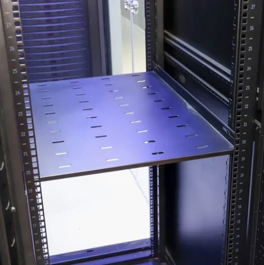
| Internal fittings | Mounting plate, DIN rail brackets, gland plate, earth stud |
| Cable entry | Bottom, top or rear, through removable gland plates |
| MOQ | 20 units (single units accepted for prototypes) |
| Lead Time | 25-30 days after drawing approval |
| Sample Time | 15-20 days |
| Applications | PLC and control cabinets, drive cabinets, robot controller housings, HMI stations, junction boxes |
| Compliance | Fabricated to the dimensional and material requirements of IEC 62208. Type testing and certification remain with the equipment builder or a third-party test house. |
What Counts as an Industrial Automation Enclosure
An automation enclosure is not a single product. It is whatever sheet metal shell the control system needs: the cabinet that holds the PLC and its I/O, the one that holds the drives, the operator station on the machine, the junction box at the end of the line. What they share is that the internal envelope, the apertures and the cable entry are all decided by somebody else’s electrical design — which is why the drawing review matters more here than on a general-purpose enclosure.
| What we build | Typical use | What the enclosure has to get right |
|---|---|---|
| PLC and control cabinets | Line control, I/O racks, safety relays | Mounting plate area, DIN rail spacing and the depth needed behind the door for wiring bends |
| Drive and inverter cabinets | Motor drives, servo amplifiers, soft starters | Heat rejection and cable separation between power and signal wiring |
| Robot controller housings | Cell-side controllers and teach pendants storage | Rigidity, because the unit is often moved or re-sited with the cell |
| HMI and operator stations | Panel-mounted screens and pushbutton clusters | Cut-out accuracy, viewing angle and access from the operator side |
| Machine-mounted control boxes | Control boxes bolted onto the machine frame | Mounting interface and stiffness, so the box does not drum or twist |
| Junction and terminal boxes | Field wiring, sensor and actuator marshalling | Gland plate layout, entry direction and terminal rail fixing |
How an Automation Enclosure Is Fabricated and Checked
The stages below are the same for one cabinet or a line build of forty. What changes with volume is the tooling, not the sequence.
| Stage | What happens | What is verified before the job moves on |
|---|---|---|
| Drawing review | Component layout, aperture schedule and cable entry are checked against the shell geometry | Whether every component actually fits inside the internal envelope with room for wiring bends and clearance distances |
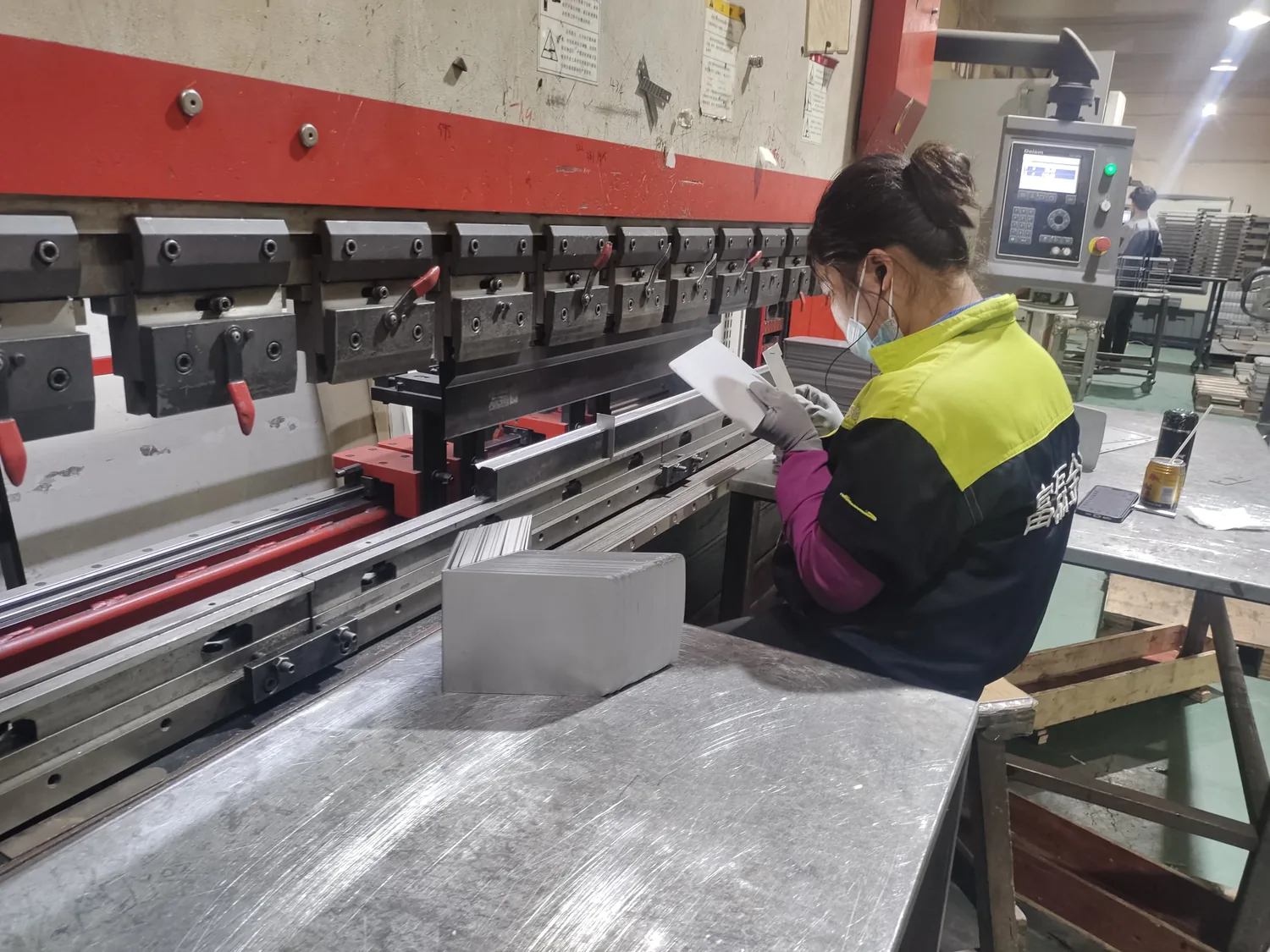
| Shell forming | Body, doors, mounting plate and gland plates cut and formed | The internal clear dimensions and the mounting plate fixing pattern, which decide whether the components will fit on site |
| Cut-outs and apertures | HMI, gland, fan, filter and cable entries made | Aperture position, size and burr condition. A burr left at a gland plate damages cable insulation during installation |
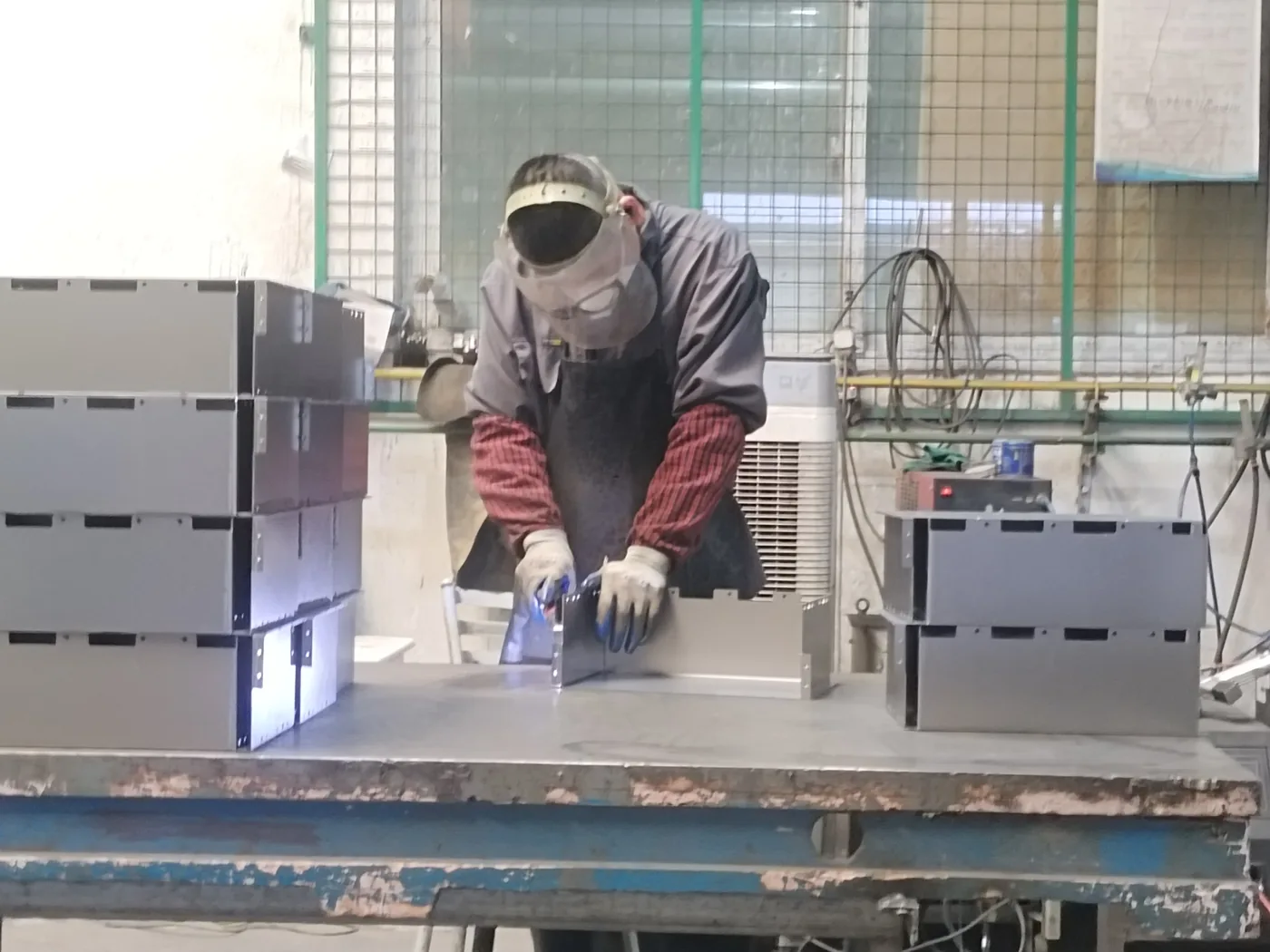
| Frame and seam welding | Corner seams and the door frame welded, with reinforcement where the weight sits | Diagonals across the door opening, and the door frame checked for twist before hinges are fitted |
| Door, hinge and gasket | Hinges, lock, handle and sealing gasket fitted | Door alignment, gasket compression and lock engagement, checked with the door closed on the finished gasket |
| Surface preparation and coating | Degrease, phosphate, then powder coat with masking at earth studs and gland areas | Film thickness, coverage inside corners, and that the masked areas are genuinely clear of coating |
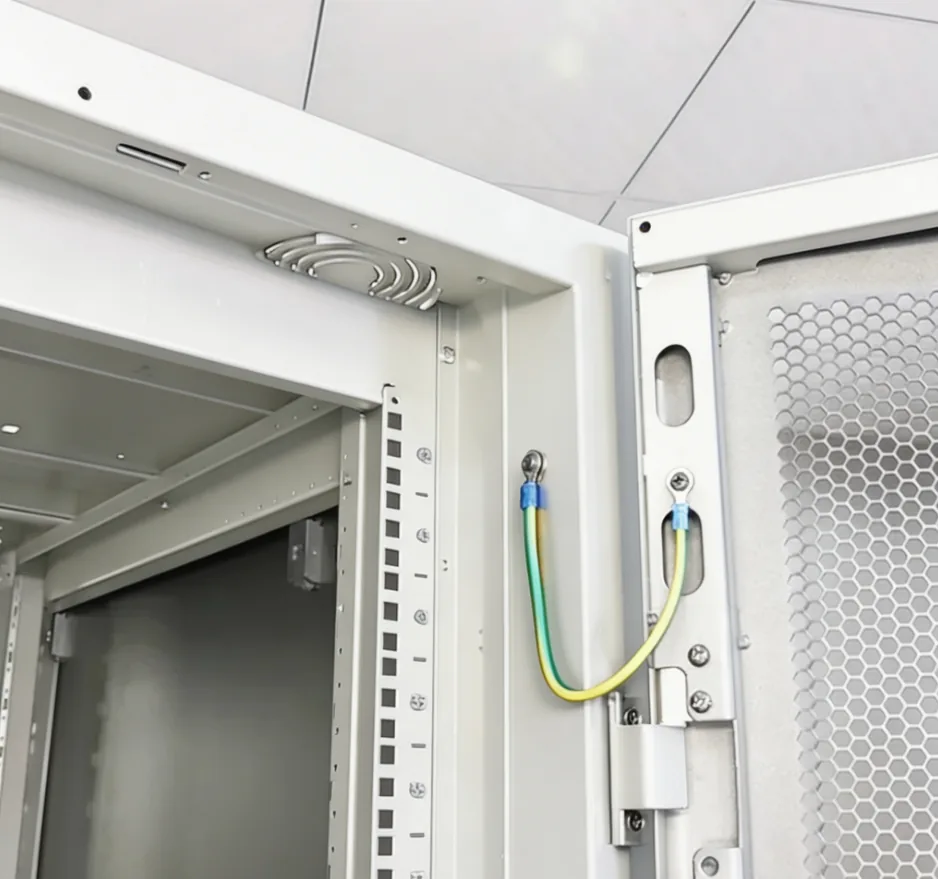
| Assembly and continuity | Mounting plate, cable management, door stay and hardware fitted | Continuity between door and body through the bonding strap, plus hardware torque |
| Packing | Doors braced, unit wrapped, corners and edges protected | The packed unit against the packing specification. The door and its hinges are the vulnerable part in transit |
Six Decisions That Decide Whether the Cabinet Works on Site
Most automation enclosure problems we are asked to fix are not manufacturing faults. They are decisions that were never made at drawing stage, and then had to be solved on site with a drill.
| Decision | Why it matters | What we need from you |
|---|---|---|
| How the heat leaves | Drive cabinets reject far more heat than PLC cabinets. A sealed IP65 cabinet holding drives will overheat unless the heat path is designed in from the start | The total dissipation in watts, and whether filtered fans, a louvred vent panel or a heat exchanger is acceptable in the environment |
| Where cables enter | Cable entry drives the gland plate layout, the frame reinforcement and whether the cabinet can be pushed back against a wall | Entry face (top, bottom, rear), the number and size of glands, and whether screen bonding is needed at the entry point |
| Depth behind the door | Wiring needs bending room. Cabinets that are dimensionally correct but too shallow are the most common rework we see | Terminal block depth, wire duct size and the minimum bend radius the wiring spec allows |
| Protection rating | The rating changes the gasket, the door stiffness and how every aperture is treated — not the sheet thickness | The IP rating the site actually requires, and whether washdown or hose-directed water is involved |
| Earthing and bonding | Coating between the bonding point and the frame is a continuity fault that only shows up at commissioning | Whether the bonding points are on the mounting plate, the door or both, and whether the site requires a dedicated earth bar |
| Line and batch consistency | On a line build, cabinets stand next to each other. Different plinth heights or cable trunking positions look like a mistake even when each unit is within tolerance | The full cabinet schedule, so shared dimensions such as plinth height and trunking centre lines can be fixed across the batch |
What Can Be Changed Without New Tooling
Customisation is mostly about the internal envelope and the apertures, because those are what the electrical design depends on.
| What can be changed | What it affects | What it does not affect |
|---|---|---|
| External dimensions and internal depth | Panel sizes, mounting plate size and the packing | The protection concept, as long as the gasket and door design stay the same |
| Single or double door | Hinge count, lock type and the swing clearance needed on site | The internal mounting plate |
| Mounting plate type and hole pattern | Component layout and fixing positions | The shell |
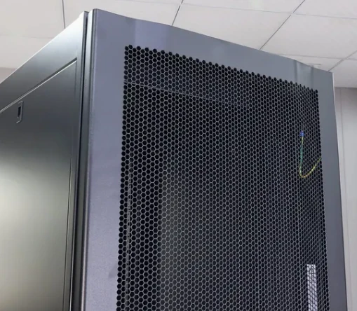
| Aperture schedule | HMI cut-outs, gland plates, fan and filter openings | The frame, within the limits of the panel width |
| Protection rating | Gasket specification, door stiffness and how apertures are treated | The external dimensions |
| Cable entry face and layout | Gland plate position and the cut-outs behind it | The frame |
| Colour, finish and marking | Powder specification, labelling and identification plates | Nothing structural |
Checks We Run on Every Batch
- Dimensional — outside dimensions, door opening diagonals and mounting plate fixing centres against the approved drawing.
- Fit — hinges, lock and gasket checked with the door closed on the finished gasket, not on a bare frame.
- Coating — film thickness and coverage, with the masked bonding and gland areas confirmed clear of powder.
- Continuity — bond resistance between door and body through the earth strap, recorded per unit.
- Apertures — each cut-out checked against the aperture schedule before the unit is packed.
- Packing — door braced, unit wrapped, corners protected, and the pallet marked for the destination.
Standards: What We Build To, and What We Do Not Certify
We are the sheet metal fabricator, not the equipment manufacturer. Our scope covers the enclosure as a mechanical part: the material, the sheet thickness, the forming and welding, the coating and the dimensional accuracy.
Where a standard governs the enclosure itself — for example IEC 62208 for empty enclosures — we fabricate the shell to that standard’s dimensional, material and coating requirements. The certification of the finished assembly, and any type test of the enclosure as part of an electrical product, is carried out by the equipment builder or a third-party test house, because the result depends on the components installed, the wiring and the final assembly, none of which are within our scope.
If your project needs a specific declaration or test evidence, say so at enquiry stage and we will tell you what we can supply from our side and what has to sit with you.
Frequently Asked Questions
What is the difference between an automation enclosure and a control panel enclosure?
An automation enclosure is the container for a control system — it may hold a PLC, drives, safety relays and the field wiring all at once, and it is usually sized around a cabinet schedule rather than a single component. A control panel enclosure is typically one panel with an HMI or pushbutton cluster. In practice the two overlap, and we build both. If your project is a single panel rather than a system cabinet, see industrial control panel enclosures.
Can you build a line where every cabinet is a different size?
Yes, and this is where a fabricator with its own drawing review earns its keep. Send the whole cabinet schedule at once rather than the cabinets one at a time. Shared dimensions — plinth height, cable trunking centre line, door swing direction, lock type — should be fixed across the batch so the units still line up when they are bolted together on site.
How does heat get out of a sealed cabinet?
It has to be designed in. A sealed IP65 enclosure rejects heat only through its surfaces, which is rarely enough for a drive cabinet. The usual options are a filtered fan with a louvred outlet, a vent panel with a defined open area, or a heat exchanger that keeps the internal air separate from the plant air. What matters is that the open area and the fan position are decided at drawing stage, because a vent cannot be added cleanly once the panel is coated.
Will you supply one unit before we commit to a batch?
Yes. A single unit is the cheapest way to prove the internal envelope, the aperture positions and the door operation against the real components. It takes 15–20 days, and the forming programme carries over to the batch, so the prototype is not wasted work.
What do you need from us to quote?
The enclosure drawing or a dimensioned sketch; the component layout if it is fixed; the aperture schedule; the cable entry face and gland sizes; the material and IP rating; the colour; and the quantity and delivery date. If the drawing is not final, send what exists — the review is more useful before the drawing is frozen than after. Send it through the RFQ form.
Related reading: automation equipment sheet metal fabrication, control cabinet manufacturing process, enclosure assembly service and custom metal enclosure manufacturing.