
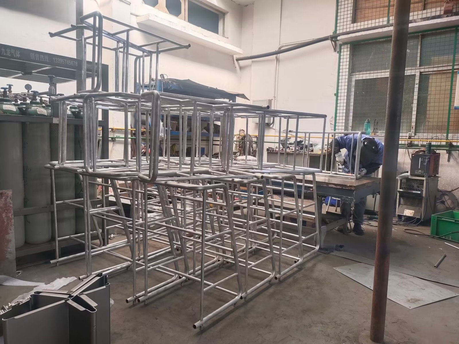
At Fulei Metal, we weld stainless steel every day — from 0.8 mm enclosures for Korean electronics brands to 3 mm structural frames for European equipment manufacturers. When a customer asks us to weld stainless, the first question we ask ourselves is: TIG or MIG? For visible and precision-critical work on stainless, the answer is almost always TIG. Here’s a practical guide based on what we’ve learned running 10 welding stations in our Ningbo factory.
Why TIG is the preferred process for stainless steel
TIG (GTAW per AWS A5.12) gives us three things that matter for stainless steel OEM work: clean, spatter-free welds; precise heat control that prevents carbide precipitation; and the ability to weld thin material — down to 0.5 mm — without burn-through. When a customer’s part has visible welds that need to look consistent from unit to unit, we default to TIG.
The difference is visible. A MIG weld on 1.5 mm 304 stainless will have spatter that needs post-weld grinding. A TIG weld on the same part comes out clean and silver — we often deliver TIG-welded stainless parts with zero post-weld finishing, which saves 15–20 minutes per part on cosmetic enclosures.
Shielding gas: pure argon vs. argon-hydrogen mixes
For 90% of our stainless TIG work, we use pure argon (99.99%) flowing at 10–15 L/min through a gas lens nozzle. Pure argon works for 304, 316, and 430 stainless from 0.5 mm up to about 4 mm thickness in a single pass.
For thicker sections (5 mm and above) or when we need higher travel speed on production runs, we add 2–5% hydrogen to the argon. The hydrogen increases arc heat, widens the weld pool slightly, and improves wetting — the edges of the weld bead flow more smoothly into the base metal. Our operators use an Ar + 3% H₂ mix on 3 mm 316L enclosures where cosmetic appearance is critical and cycle time matters.
One caution: hydrogen can cause porosity in some ferritic stainless grades. We’ve learned to test the gas mix on a sample coupon before committing to a production lot.
Filler rod selection: get this right first
Using the wrong filler rod is the fastest way to ruin a stainless weld. The weld metal must match or slightly over-alloy the base metal to avoid galvanic corrosion or reduced mechanical properties.
| Base Metal | Filler Rod (AWS) | Typical Application | Key Property |
|---|---|---|---|
| 304 / 304L | ER308L (AWS A5.9) | Food equipment, enclosures, architectural | 18Cr-8Ni, matches base metal |
| 304 to mild steel | ER309L | Dissimilar metal joints, brackets, mounting plates | 23Cr-13Ni, high ferrite resists cracking |
| 316 / 316L | ER316L | Marine, chemical, medical — where Mo is needed | 18Cr-12Ni-2.5Mo, pitting resistance |
| 316 to 304 | ER309L or ER316L | Transition joints | Use 309L for structural, 316L for corrosion |
| 321 | ER347 | Exhaust systems, elevated temperature | Nb-stabilized, retains strength at temp |
| 430 | ER430 or ER309L | Automotive trim, appliance panels | 17Cr, ferritic — lower cost than 304 |
Our shop standard is 1.6 mm diameter filler for material up to 2 mm, and 2.4 mm for 3 mm and above. For thin sheet (0.8–1.2 mm), we drop to 1.2 mm or even 0.8 mm rod to match the smaller weld pool.
Torch technique: what good welders do differently
We’ve trained over 20 TIG welders in our factory, and the technique differences between a trainee and a seasoned hand are measurable:
- Torch angle: 10–15° from vertical, pushing the puddle forward. Anything steeper overheats the gas lens; anything shallower draws air into the shielding envelope.
- Arc length: 1.5–3.0 mm for stainless. A long arc — 5 mm or more — pulls oxygen into the weld pool and creates a gray, oxidized bead. We train operators to keep the tungsten tip just above the puddle surface.
- Travel speed: On 1.5 mm 304, our standard speed is 120–150 mm/min with 60–80 A DCEN. Pushing faster than 180 mm/min tends to produce a convex bead with poor tie-in at the edges.
- Filler rod addition: Dip the rod into the leading edge of the puddle, not the arc. Adding filler directly into the arc vaporizes alloying elements — you’ll see a white fume that contains chromium.
The #1 defect we see: sugaring on the back side
Sugaring — a black, granular oxide crust on the back side of the weld — is the most common defect in stainless TIG welding. It happens when the back side of the molten weld pool is exposed to oxygen at temperature. A sugared weld is not cosmetic damage. The chromium oxide depletion leaves a chromium-depleted zone underneath; the part will rust at that location.
Per ASME B31.3 and AWS D1.6 structural welding code for stainless, sugared welds on the root side are rejectable defects. The solution is back-side purge gas, and we use three methods depending on the part geometry:
- Full enclosure purge: For enclosures and boxes, we fabricate a simple purge fixture — essentially a chamber filled with argon that floods the inside of the part. Argon flow rate is 15–20 L/min, and we wait until an oxygen analyzer reads below 0.5% O₂ before striking the arc.
- Trailing purge shoe: For long butt welds on sheet, a copper or aluminum backing bar with a gas distribution channel runs along the back side of the seam. This is our go-to for seams longer than 300 mm.
- Solar flux (backing flux): For field joints or parts where purge fixturing is impractical, we apply a proprietary backing flux to the back side. It melts and forms a glassy slag that shields the weld root. Not as clean as argon purge, but acceptable for non-code work where the back side won’t be visible.
Our rule: if the back side of the weld is visible in the finished product, it gets argon purge. If it’s hidden inside a sealed enclosure, we’ll evaluate whether solar flux is sufficient. For food-grade 304 and marine 316L work, purge gas is mandatory.
Distortion: the thin stainless challenge
Thin stainless distorts more than mild steel at the same thickness because stainless has lower thermal conductivity — about 15 W/m·K for 304 vs. 45 W/m·K for carbon steel. The heat stays localized, creates a steep thermal gradient, and the part warps. Here’s what we do:
- Clamp everything: For sheet under 1.5 mm, we fixture within 50 mm of the weld seam on both sides. Even a 2 mm gap under the part will let it curl during welding.
- Skip welding: On long seams (400 mm+), we weld 50–80 mm segments, skip 100 mm, weld the next, then come back. This distributes shrinkage along the seam instead of concentrating it.
- Pre-set offset: For U-channel and angle sections, we pre-bend the part 1–2° opposite the expected distortion direction. The weld shrinkage pulls it back to true.
- Heat input discipline: We aim for a heat input of 0.3–0.6 kJ/mm for thin stainless (calculated as V × A × 60 / travel speed / 1000). Anything above 0.8 kJ/mm on 1.2 mm material will visibly warp.
Carbide precipitation and why L-grade matters
Between 450°C and 850°C, chromium carbides precipitate at stainless grain boundaries. This “sensitization” depletes chromium adjacent to the grain boundary, and the steel loses its corrosion resistance in that narrow zone. This is why you always specify 304L or 316L (L = low carbon, max 0.03% C) for welded structures — the lower carbon content dramatically reduces carbide precipitation.
In our factory, we track interpass temperature religiously on code work. We keep interpass below 150°C for austenitic stainless. If the part is too hot to touch bare-handed, it’s time to let it cool. On thick sections where cooling is slow, we use forced air or a water-cooled copper chill bar to pull heat out.
Practical production tips from our shop floor
- Dedicated stainless tools: We keep separate wire brushes, grinding discs, and clamps for stainless and carbon steel. Cross-contamination from carbon steel dust will cause surface rust spots on stainless within weeks.
- Electropolish for the best finish: On visible stainless welds, we offer electropolishing as a post-weld treatment. It removes the heat tint, passivates the surface, and leaves a bright, uniform finish. It also removes surface iron contamination.
- Fit-up tolerance: Keep your gap below 0.5 mm for autogenous TIG (no filler) and below 1.5 mm for filler-added TIG. A gap larger than the filler rod diameter makes the operator’s job much harder and increases the risk of burn-through.
- Tungsten type: Use 2% thoriated (red tip) or 2% lanthanated (blue tip) tungsten, ground to a point with the grinding marks parallel to the electrode axis. A blunt or contaminated tungsten will produce an unstable arc that wanders.
TIG welding stainless is a skill, but it’s a repeatable one. Once you dial in the gas, the rod, the amperage, and the fixture, the process is predictable. If you’re designing a stainless part and wondering whether TIG is the right call, send us your drawing and we’ll tell you what works — and what doesn’t — based on ten years of doing this every day.
Need TIG Welding for Stainless Steel Parts?
Send us your drawing. We’ll review it, recommend the right filler rod and welding process, and quote within 24 hours — including purge gas fixturing if your part needs it.