
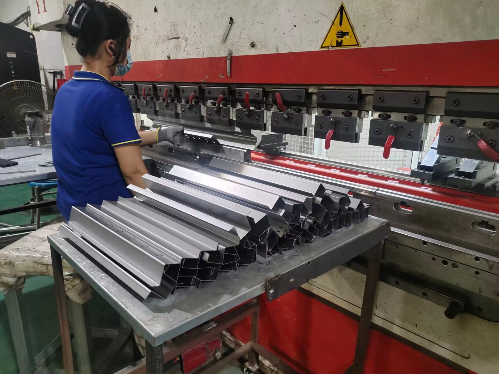
Bend radius is one of the most common things designers get wrong in sheet metal drawings. Too small and the part cracks. Too large and it eats into adjacent features, wastes material, and looks wrong. At Fulei Metal, we bend thousands of parts a week on four CNC press brakes, and we’ve seen every radius mistake in the book. This guide covers the rules we follow so your parts come out right the first time.
Why bend radius matters
When you bend sheet metal, the outer surface stretches and the inner surface compresses. The bend radius — measured to the inside of the bend — determines how much stretching happens on the outer fiber. A smaller radius means more stretch. Push it past the material’s elongation limit and the outer surface cracks. That’s the fundamental constraint.
But there’s more to it than avoiding cracks. The bend radius also affects:
- Flat pattern accuracy: The radius determines how much material is “consumed” in the bend, which directly affects your flat blank length. Get the radius wrong and your folded part won’t match the designed dimension. (We cover this in detail in our article on K-factor and bend allowance.)
- Springback: Larger radii produce more springback, which means the press brake operator needs to overbend further to hit the target angle.
- Tooling compatibility: The radius you get in air bending is determined by the V-die opening, not the punch tip. A designer who calls out a 0.5 mm radius on 3 mm steel is asking for something that requires coining — a different, more expensive process.
Minimum bend radius rules by material
The minimum bend radius is expressed as a multiple of material thickness (T). Here are the rules of thumb we use, consistent with ISO 6707 and common industry practice (e.g., DIN 6935 guidelines):
| Material | Min Bend Radius (air bending) | Notes |
|---|---|---|
| Mild steel (CRS, e.g., SPCC/DC01) | 1.0T | Most forgiving; can sometimes go to 0.5T with coining |
| Hot-rolled steel (SPHC) | 1.0T | Scale surface may crack at smaller radii |
| Stainless steel 304 | 1.5T | Work-hardens aggressively; small radii crack easily |
| Stainless steel 316 | 1.5–2.0T | More prone to cracking than 304 |
| Aluminum 5052-H32 | 1.5T | Good formability among aluminum alloys |
| Aluminum 6061-T6 | 2.5–3.0T | Poor bendability; cracks at small radii |
| Aluminum 5052-O (annealed) | 0.5T | Very soft; can take tight bends |
| Brass (C260, half-hard) | 1.0T | Good formability |
| Copper (C110, soft) | 0.5T | Very ductile |
The key takeaway: aluminum is not aluminum. 5052-H32 bends nicely at 1.5T. 6061-T6 will crack at anything under 2.5T and even then, we recommend testing. If your design specifies 6061-T6 with a 1T bend radius, we will flag it before production — because it will fail.
Why too-small radius causes cracking
Cracking happens when the outer fiber elongation exceeds the material’s ultimate elongation. The math is straightforward. For a 90° bend with inside radius R and thickness T, the outer fiber elongation is approximately:
Elongation ≈ T / (2R + T) × 100%
For mild steel with ~20% elongation, a radius of 1.0T gives about 33% nominal elongation on the outer fiber — but localized strain at the surface is lower than the nominal because the neutral axis shifts inward. That’s why 1.0T works in practice even though the raw number looks high. For 6061-T6 aluminum with ~10% elongation, a 1.0T radius pushes the outer fiber past its limit, and you get a visible crack on the outside of the bend.
Cracking is also worse when the bend line is perpendicular to the grain direction (more on this below). If you must use a tight radius, align the bend line parallel to the rolling direction — it can buy you 20–30% more formability on some materials.
Material thickness and minimum radius
The “Rmin = 1T” rule scales with thickness, which is both convenient and sometimes misleading. Here’s what it looks like for common thicknesses of mild steel (SPCC):
| Thickness (mm) | Min Radius (1.0T) | Preferred Radius (1.5–2.0T) |
|---|---|---|
| 0.8 | 0.8 mm | 1.2–1.6 mm |
| 1.0 | 1.0 mm | 1.5–2.0 mm |
| 1.5 | 1.5 mm | 2.25–3.0 mm |
| 2.0 | 2.0 mm | 3.0–4.0 mm |
| 3.0 | 3.0 mm | 4.5–6.0 mm |
| 4.0 | 4.0 mm | 6.0–8.0 mm |
| 6.0 | 6.0 mm | 9.0–12.0 mm |
We recommend designing to 1.5–2.0T whenever the design allows. It costs you nothing, gives the operator a wider process window, and eliminates the risk of edge cracking in production. The only time you should specify a minimum radius is when the geometry forces it — and in that case, call it out explicitly so the shop knows to use coining or a tighter V-die.
How grain direction affects bending
Sheet metal has a grain — the direction of rolling at the mill. Bending perpendicular to the grain (across it) puts the outer fiber in tension across the grain boundaries, which are weaker. Bending parallel to the grain (along it) is more forgiving because the stress runs along the grain boundaries.
In practice, this means:
- Bend line perpendicular to grain: Higher cracking risk. Increase radius by 20–50% above the minimum, especially on aluminum and stainless.
- Bend line parallel to grain: Lower cracking risk. You can safely use minimum radius.
Most production sheets come with grain direction marked. At Fulei Metal, we note grain direction on the nesting layout for parts with tight radii or crack-prone materials (6061 aluminum, 316 stainless). For high-volume jobs, we’ll orient the nest so that critical bend lines run parallel to grain. This is a detail that most shops won’t mention unless you ask — but it’s the difference between a 0% and a 5% scrap rate on difficult materials.
Air bending vs bottom bending vs coining
The bending method determines how precisely you can control the radius:
Air bending (most common)
The punch presses the sheet into the V-die without bottoming out. The radius is determined primarily by the V-die opening width, not the punch tip. Rule of thumb: the achieved inside radius ≈ V-die opening × 0.15 to 0.17 for mild steel. So a V-die opening of 24 mm gives you roughly a 3.6–4.1 mm inside radius.
Air bending is flexible — one set of tooling can produce different radii by changing the die opening — but it has more springback and less radius precision (±0.5 mm typically). It’s the right choice for 90% of our bending work.
Bottom bending (bottoming)
The sheet is pressed to the bottom of the V-die, with the die angle matching the target angle. Bottoming reduces springback significantly and gives better radius control (±0.2 mm). It requires more tonnage — roughly 3–5x air bending — and dedicated tooling for each angle. We use it for parts that need tight angle tolerance (±0.5°) like our electrical enclosure door frames.
Coining
The punch fully compresses the material into the die, imprinting the exact radius and angle. Springback is essentially zero. Radius precision is ±0.05 mm. But coining requires enormous tonnage — 5–10x air bending — and is limited to thinner gauge (typically ≤3 mm). It also wears tooling faster. We use coining only when a design absolutely requires a radius smaller than the air-bending minimum, such as tight corners on cosmetic parts.
Practical tips for designers
- Default to 1.5T radius. It works on nearly all materials in air bending, gives the operator room to work, and costs nothing. Don’t specify “sharp corner” unless you genuinely need it.
- Keep radii consistent across a part. If you use 2 mm radius on one bend, use it on all bends. This lets the operator use one V-die setup, saving setup time and reducing cost. We charge for each tool change, so fewer setups means lower unit price.
- Call out radius on the drawing. Don’t leave it to the shop’s discretion. A note like “R2.0 unless otherwise specified” eliminates ambiguity and prevents rework.
- Check material against radius. If you’re specifying 6061-T6 aluminum with a 1T radius, you will get cracks. Either change the material (5052-H32 is far more bendable) or increase the radius. We review every drawing for this — but not all shops do.
- Account for radius in flat pattern. Use the correct K-factor for your material and bending method. Our K-factor guide covers the specifics.
- Leave flange length for the V-die. A flange shorter than about 4× the V-die opening can’t be bent in a standard die because the material won’t reach across the opening. For a 3 mm sheet with a 24 mm V-die, the minimum flange is about 15 mm. Shorter flanges require special tooling or a smaller die (which changes the radius).
Get the radius right at the design stage and your parts will bend cleanly, fit together in assembly, and cost less to produce. If you’re unsure, send us your drawing and our engineering team will review your bend radii before we cut metal.
Need Help With Your Bend Design?
Send us your drawing and our engineers will review your bend radii, material selection, and flat pattern before production. Free DFM review for serious projects.