
If there’s one problem we see in nearly every new sheet metal project at Fulei Metal, it’s welding distortion. A customer sends us a perfectly flat laser-cut blank, we weld it, and it comes out warped by 2–3 mm. The part doesn’t mate with its counterpart. Assembly takes twice as long. The customer asks what went wrong. The answer: nothing went wrong — distortion is physics. The question is whether you planned for it. Here’s how we control distortion on our factory floor.
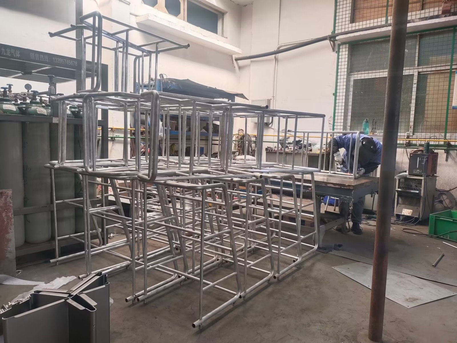
Why distortion happens: it’s all about differential thermal expansion
When you weld, you’re heating a narrow strip of metal to 1,500°C while the surrounding material stays at room temperature. The hot metal wants to expand. The cold metal around it resists. The result is compressive plastic deformation in the heated zone — the metal yields because it’s soft at high temperature, and it gets squeezed shorter by the surrounding cold material.
When the weld cools, it tries to contract back to its original length. But it’s now slightly shorter than it was before — it’s been plastically compressed. So when it contracts and reaches room temperature, it pulls the surrounding material inward, creating angular distortion (the part bends toward the weld side) and longitudinal shrinkage (the part shortens along the weld axis).
The math: for a 300 mm seam on 1.5 mm mild steel, the longitudinal shrinkage is typically 0.5–1.5 mm per 300 mm. Angular distortion can reach 2–5° if not controlled. On thin sheet (≤2 mm), angular distortion is the dominant problem. On thicker plate (≥6 mm), longitudinal and transverse shrinkage dominate.
Factors that increase distortion
Four variables control how much a welded part will distort, and we control them on every job:
- Heat input: Every joule you put into the weld becomes a problem you have to solve. The heat input formula (per AWS D1.1): Q = (V × A × 60) / (travel speed × 1000) in kJ/mm. At 80 A, 12 V, and 120 mm/min, Q = 0.48 kJ/mm. Drop the current to 65 A and speed up to 150 mm/min, and Q drops to 0.31 kJ/mm — a 35% reduction. This is the single most powerful lever you have.
- Weld sequence: The order in which you deposit welds determines where the shrinkage forces go. A poorly sequenced weld — welding all four corners of a frame clockwise — concentrates all the shrinkage in one direction. A balanced sequence distributes it.
- Joint design: Single-sided fillet and butt welds on thin sheet are the worst offenders because all the contraction is on one side of the neutral axis. Double-sided welds, intermittent welds, or joints designed with the weld on or near the neutral axis reduce distortion significantly.
- Material properties: Stainless steel (304, 316) distorts about 1.5× more than carbon steel at the same heat input because its thermal conductivity is one-third that of carbon steel. Aluminum (5052, 6061) distorts even more — roughly 2–3× carbon steel — because its coefficient of thermal expansion is twice as high and its thermal conductivity pulls heat away quickly, creating a steeper gradient.
Six distortion control techniques we use daily
1. Weld sequencing: skip welding and back-step welding
On long seams (300 mm or more), instead of running a continuous bead from start to finish, we weld in segments. Skip welding: weld 50–80 mm, skip 100 mm, weld the next segment, then come back and fill the gaps. This distributes the shrinkage along the seam instead of concentrating it at the end. On a 400 mm seam with four 80 mm segments, skip welding reduces angular distortion by 40–60% compared to a single continuous pass.
Back-step welding is similar but reversed: each segment is welded in the opposite direction of the overall seam progress. So if the seam runs left to right, each 60 mm segment is welded right to left. This balances the contraction strains. We use back-step welding on 304 stainless frames where even 1 mm of distortion is a reject.
2. Clamping and fixturing
For sheet metal under 2 mm, clamping within 50 mm of the weld seam on both sides is non-negotiable. We use purpose-built steel or aluminum fixture plates with toggle clamps. The fixture must be rigid enough that the part can’t lift — if you can slide a 0.2 mm feeler gauge between the part and the fixture during welding, the fixture isn’t doing its job.
For production runs of 100+ identical parts, we invest in a machined copper or aluminum backing bar — copper because it conducts heat away from the weld zone, acting as a heat sink that shrinks the HAZ and reduces distortion. A copper chill bar can reduce angular distortion by 50–70% on thin stainless.
3. Pre-bending and pre-setting offset
This is an old shipyard technique that works beautifully on sheet metal. Before welding, we bend the parts 1–3° in the direction opposite to the expected distortion. When the weld cools and shrinks, it pulls the part back to flat. On a U-channel section with a 200 mm butt weld on one flange, we pre-set 2° of counter-bend at the press brake. Post-weld, the part measures within 0.5° of true.
The offset amount comes from experience with the specific part. We do a trial weld on the first article, measure the distortion, and set the pre-bend for production accordingly. It takes one extra bending operation but eliminates straightening labor downstream.
4. Welding in sections vs. continuous
Continuous welding maximizes distortion. Intermittent (stitch) welding — 30 mm weld, 60 mm skip, repeat — reduces heat input by 50% for the same joint length. Per AWS D1.1 and D1.3, intermittent welds are fully acceptable for non-sealed joints where the design strength requirements are met. For a sheet metal enclosure that only needs structural integrity, not a pressure seal, stitch welding with a 30/60 pattern typically cuts distortion in half with no loss of function.
5. Thermal stress relief
For carbon steel parts that can tolerate it, post-weld vibratory stress relief (VSR) or thermal stress relief at 600–650°C for 1 hour per 25 mm of thickness can reduce residual stresses by 60–80%. In a sheet metal context, VSR is more practical than furnace stress relief — it’s faster, cheaper, and doesn’t cause scale or oxidation on the part surface. We use VSR on large welded frames and structural assemblies where even 2 mm of spring-back after welding would cause assembly problems.
6. Heat input discipline — the single most effective control
Every one of our welders knows their target heat input range for the material they’re welding. We post these on each welding station:
| Material | Thickness | Target Q (kJ/mm) | Typical parameters |
|---|---|---|---|
| CRS / mild steel | 1.0–1.5 mm | 0.20–0.35 | 60–75 A, 12 V, 150 mm/min |
| CRS / mild steel | 2.0–3.0 mm | 0.35–0.50 | 80–100 A, 13 V, 130 mm/min |
| 304 stainless | 1.0–1.5 mm | 0.15–0.25 | 50–65 A, 11 V, 150 mm/min |
| 304 stainless | 2.0–3.0 mm | 0.25–0.40 | 65–85 A, 12 V, 130 mm/min |
| 5052 aluminum | 1.5–2.0 mm | 0.30–0.45 | 120–150 A, 14 V, 200 mm/min |
| 6061 aluminum | 2.0–3.0 mm | 0.40–0.60 | 150–180 A, 15 V, 180 mm/min |
If a welder consistently exceeds the target heat input, parts come out warped. If they push too low, they risk lack of fusion. The sweet spot is narrow, and we train our operators to find it and stay there.
Material-specific distortion behavior
Cold-rolled steel (CRS, 1.0–3.0 mm): Moderate distortion. Our primary material, and the most forgiving. A well-fixtured CRS part with controlled heat input and balanced sequencing will come out flat. This is where 80% of our distortion-control effort goes because it’s 80% of our volume.
304/316 stainless (0.8–3.0 mm): High distortion — 1.5× CRS. We always use a copper chill bar, skip welding on seams longer than 200 mm, and pre-set offset on anything with a single-sided weld. Purge gas on the back side helps slightly by reducing the peak temperature at the root, but it’s not a substitute for proper fixturing.
Aluminum 5052/6061 (1.0–4.0 mm): Worst distortion — 2–3× CRS. Aluminum’s high thermal expansion and high conductivity combine to create a recipe for severe warping. We always preheat aluminum to 120–150°C before TIG welding to reduce the thermal gradient. We never skip-weld aluminum — instead, we use continuous welding with aggressive copper chill bars and heavy clamping. Aluminum distortion is a fight, and you win it with preparation, not technique adjustments during the weld.
Practical tips from our shop floor
- Tack weld before committing: Place tacks every 50–80 mm along the seam before running the full bead. This pre-locates the parts and prevents the gap from opening as the weld progresses.
- Weld from the center outward: On a seam with both ends free, start in the middle and weld toward each end. The shrinkage is symmetric, and the final distortion is lower.
- Alternate sides on multi-pass welds: If a joint needs two passes, weld the first pass, flip the part, weld the second pass on the opposite side. The second pass’s shrinkage counteracts the first.
- Don’t over-weld: A 4 mm fillet weld on 1.5 mm sheet is overkill — it adds heat without adding strength. Size the weld to the thinner member per AWS D1.3 Table 3.1.
- Let the part cool between passes: If the part is too hot to touch bare-handed, wait. Our interpass temperature limit for stainless is 150°C; for CRS, 200°C.
Distortion isn’t something you fix after welding — it’s something you control before you strike the arc. If you’re designing a sheet metal assembly and want to avoid distortion problems before they happen, send us your drawing. We’ll review the weld design and tell you where the distortion risks are, and how we’d manage them in production.
Worried About Welding Distortion on Your Parts?
Send us your drawing. We’ll review the weld design, identify distortion risks, and propose control measures — fixturing, sequencing, and pre-bend offsets — before we quote.