
At Fulei Metal, we run four CNC press brakes — two 100-ton and two 160-ton machines. Over the years, we’ve built up a tooling library of more than 200 punches and dies. Choosing the right tooling for a job is the single biggest factor in bend quality, dimensional accuracy, and setup efficiency. Get it wrong and you get angle inconsistency, tool marks, or worse — damaged tooling. Here’s how we select punch and die for every job.
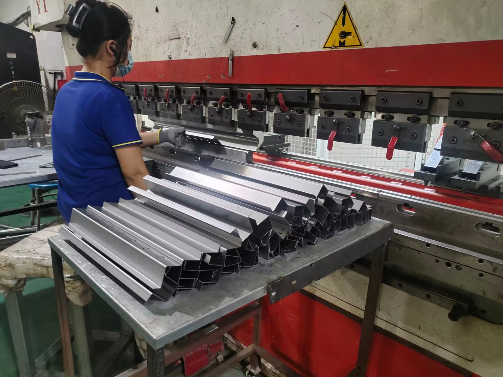
Punch types and when to use each
The punch is the upper tool — it pushes the sheet into the die. Different punch profiles serve different geometries:
Sharp punch (standard)
The most common punch, with a tip radius of 0.5–1.0 mm and a tip angle of 88° (to account for springback). Used for standard 90° bends on thin to medium gauge sheet (0.5–4 mm). It’s the default in most shops because it handles the majority of parts. We use it on our library furniture brackets and most mild steel enclosures.
Blunt punch (radius punch)
Has a larger tip radius (2–8 mm). Use this when the design calls for a large inside radius, or when bending thick material (≥5 mm) where a sharp punch would indent the inside of the bend. Also essential for aluminum — a sharp punch on 6061-T6 at 3 mm will leave a visible crease line on the inside of the bend. We use blunt punches for our livestock equipment frames, which use 4–6 mm hot-rolled steel.
Goose-neck punch
Has a curved profile that clears previously formed flanges. Essential for parts with multiple bends where a standard punch would collide with an existing up-flange. For example, a U-channel with a third bend across the web needs a goose-neck to reach in without hitting the side walls. We use these on complex electrical enclosure assemblies.
Acute (arrow) punch
Tip angle of 30° or 45°. Used for bends sharper than 90° (acute angles) and for hemming operations. An acute punch is also needed when the V-die shoulder angle is less than 90°, which some shops use to reduce springback on harder materials.
Die types and the V-die opening rule
The die is the lower tool. It’s where most of the bending physics happens — the V-die opening width determines the bend radius, the required tonnage, and the minimum flange length.
The V = 8× thickness rule
The most important rule in press brake tooling: the V-die opening should be approximately 8 times the material thickness for optimal air bending. This is the industry-standard starting point, and it’s what we use for 90% of our work.
| Material Thickness (mm) | Standard V-die Opening (mm) | Achieved Inside Radius (mm) | Min Flange Length (mm) |
|---|---|---|---|
| 0.8 | 6–8 | 1.0–1.3 | 5 |
| 1.0 | 8–10 | 1.3–1.7 | 6 |
| 1.5 | 12–14 | 2.0–2.4 | 8 |
| 2.0 | 16–18 | 2.7–3.0 | 10 |
| 3.0 | 24–25 | 4.0–4.2 | 14 |
| 4.0 | 32 | 5.3 | 18 |
| 5.0 | 40 | 6.7 | 22 |
| 6.0 | 48–50 | 8.0–8.3 | 26 |
The achieved inside radius in air bending is approximately 0.15–0.17 × V-die opening for mild steel. This is why you can’t get a 1 mm radius on 3 mm steel with a standard V-die — the 24 mm opening gives you about 4 mm. For a tighter radius, you need a smaller V-die (which increases tonnage and risk) or a different method like coining. For more on this, see our bend radius guide.
Multi-V dies
A multi-V die has multiple openings of different widths on a single die block (e.g., 4/6/8/10 mm). This lets the operator switch V-die sizes without changing the tool, saving setup time on jobs with multiple bend radii. We use multi-V dies for prototyping and low-volume work. For production runs, we switch to single-V dies because they’re stiffer and more precise.
U-die and Z-die
Specialty dies for channel (U-shaped) and offset (Z-shaped) profiles. These form two bends in a single stroke, which is faster and more consistent than two separate bends. But they require significantly more tonnage and are limited to specific geometries. We use U-dies for our cable tray brackets where the channel width is standardized.
Tonnage calculation: will your machine handle it?
Before running a bend, you need to verify the required tonnage doesn’t exceed the machine’s capacity. The standard air-bending tonnage formula is:
P = (650 × T² × L) / V
Where: P = forming force (kN), T = material thickness (mm), L = bend length (m), V = V-die opening (mm). The constant 650 is for mild steel. For stainless steel, multiply by 1.6. For aluminum, multiply by 0.5.
Here’s a tonnage reference table for mild steel, 1 meter bend length:
| Thickness (mm) | V-die (mm) | Tonnage (kN) | Tonnage (tons) | Min Machine |
|---|---|---|---|---|
| 1.0 | 8 | 81 | 8.3 | 30-ton |
| 2.0 | 16 | 163 | 16.6 | 30-ton |
| 3.0 | 24 | 244 | 24.9 | 50-ton |
| 4.0 | 32 | 325 | 33.1 | 80-ton |
| 5.0 | 40 | 406 | 41.4 | 100-ton |
| 6.0 | 48 | 488 | 49.7 | 100-ton |
| 8.0 | 64 | 650 | 66.3 | 160-ton |
| 10.0 | 80 | 813 | 82.9 | 160-ton |
For stainless steel, multiply these numbers by 1.6. A 3 mm stainless steel bend at 1 meter requires about 40 tons — still within a 100-ton machine, but a 6 mm stainless bend at 1 meter needs about 80 tons, which is getting close to the limit of a 100-ton press. Always leave 20% safety margin. We never run our 100-ton machines above 80 tons continuous load.
Also remember that tonnage is per meter. A 2-meter bend doubles the force requirement. Distributed load across the bed matters too — a short, heavy bend in the center of the bed puts more stress on the ram than the same tonnage spread across 3 meters.
Tooling material options and durability
Press brake tooling comes in several material grades, each with different durability and price:
- T8/T10 carbon tool steel: Entry-level. Hardened to HRC 45–50. Good for low-volume mild steel work. Wears faster on stainless and aluminum (aluminum galling is a problem). We use these for prototyping only.
- 42CrMo alloy steel: Hardened to HRC 48–52. The workhorse for most Chinese shops. Good balance of cost and durability for production runs of mild steel and aluminum. Most of our standard tooling is 42CrMo.
- Cr12MoV (D2) die steel: Hardened to HRC 58–62. High wear resistance, good for stainless and high-volume work. Costs 2–3x more than 42CrMo but lasts 3–4x longer on abrasive materials. We use D2 tooling for all stainless production runs.
- Carbide-tipped: Tungsten carbide inserts on the tip and V-shoulders. Extreme wear resistance (HRC 70+). Used for very high-volume production (100,000+ parts) or abrasive materials like pre-coated galvanized sheet. Expensive — we only invest in carbide for long-running dedicated part lines.
For most OEM buyers, the tooling material doesn’t directly matter — what matters is that the shop has the right tooling for your material and volume. Ask your supplier what tooling they’ll use and how many parts they’ve run on it. Worn tooling produces inconsistent bends, and a shop that won’t replace worn inserts is cutting corners you’ll pay for later.
When to use segmented tools
Segmented tooling consists of short sections (typically 50–200 mm) that bolt together to form a custom-length punch or die. We use segmented tools when:
- A part has bends of different lengths — we can configure a single setup with segments matched to each bend, rather than running separate setups.
- The part has a bend near the center of a long flange where a full-length punch would be needed but the bend itself is short — segments let us bend without a full-length tool change.
- We need to work around obstacles — for example, bending a part with a previously welded feature that would collide with a solid punch.
The downside of segmented tooling is reduced rigidity at the segment joints, which can cause slight angle variation (0.3–0.5°) at the joint locations. For precision work (±0.5° tolerance), we prefer solid tooling. For structural parts (±1° tolerance), segmented is fine and saves significant setup time.
Common tooling mistakes that cause defects
Here are the tooling errors we see most often, both in our own shop (early on) and when reviewing parts from other suppliers:
- V-die too small for the thickness. Using a 10 mm V-die on 3 mm steel (instead of 24 mm) produces a radius that’s too small, causes edge marking on the part, and increases tonnage to dangerous levels. This is the #1 mistake. It happens when operators grab the nearest die instead of the correct one to save setup time.
- V-die too large for the thickness. Using a 32 mm V-die on 1 mm steel produces an uncontrolled radius — the sheet slides around in the wide opening and you get inconsistent angles. The part looks “loose” and dimensional repeatability is poor.
- Sharp punch on thick aluminum. Leaves a deep crease on the inside of the bend and can initiate cracking. Always use a radius punch for aluminum ≥2 mm.
- Worn punch tip. A punch tip that has rounded over from wear produces a larger radius than intended and inconsistent angles. We check punch tip radius every 2,000 bends and regrind or replace as needed.
- Misaligned segments. If segmented tooling isn’t bolted together flush, there’s a step at the joint that marks the part and causes angle variation. Always check segment alignment with a straightedge before bending.
- Not accounting for tonnage concentration. Bending a short, thick part in the center of a long bed can exceed the local tonnage capacity even if the total is within spec. This can damage the machine ram. Distribute the load or use a backing plate.
At Fulei Metal, our quality system requires a first-article inspection on every new setup — we verify angle, dimension, and radius before running the batch. Tooling selection is documented in the job traveler so the same setup is used on reorders. If you want to discuss tooling for a specific part, send us your drawing and we’ll walk you through exactly which punch and die we’d use.
Have a Bending Project?
Send us your drawing and we’ll recommend the optimal punch, die, and bending method for your material and volume. Free engineering review.