
This is the exact 12-point checklist our engineering team runs through on every RFQ at Fulei Metal before we send a quote. It comes from 10 years of seeing what works, what doesn’t, and what costs our customers money. Copy it, use it on your next design, and you’ll save yourself weeks of back-and-forth and a meaningful chunk of unit cost.
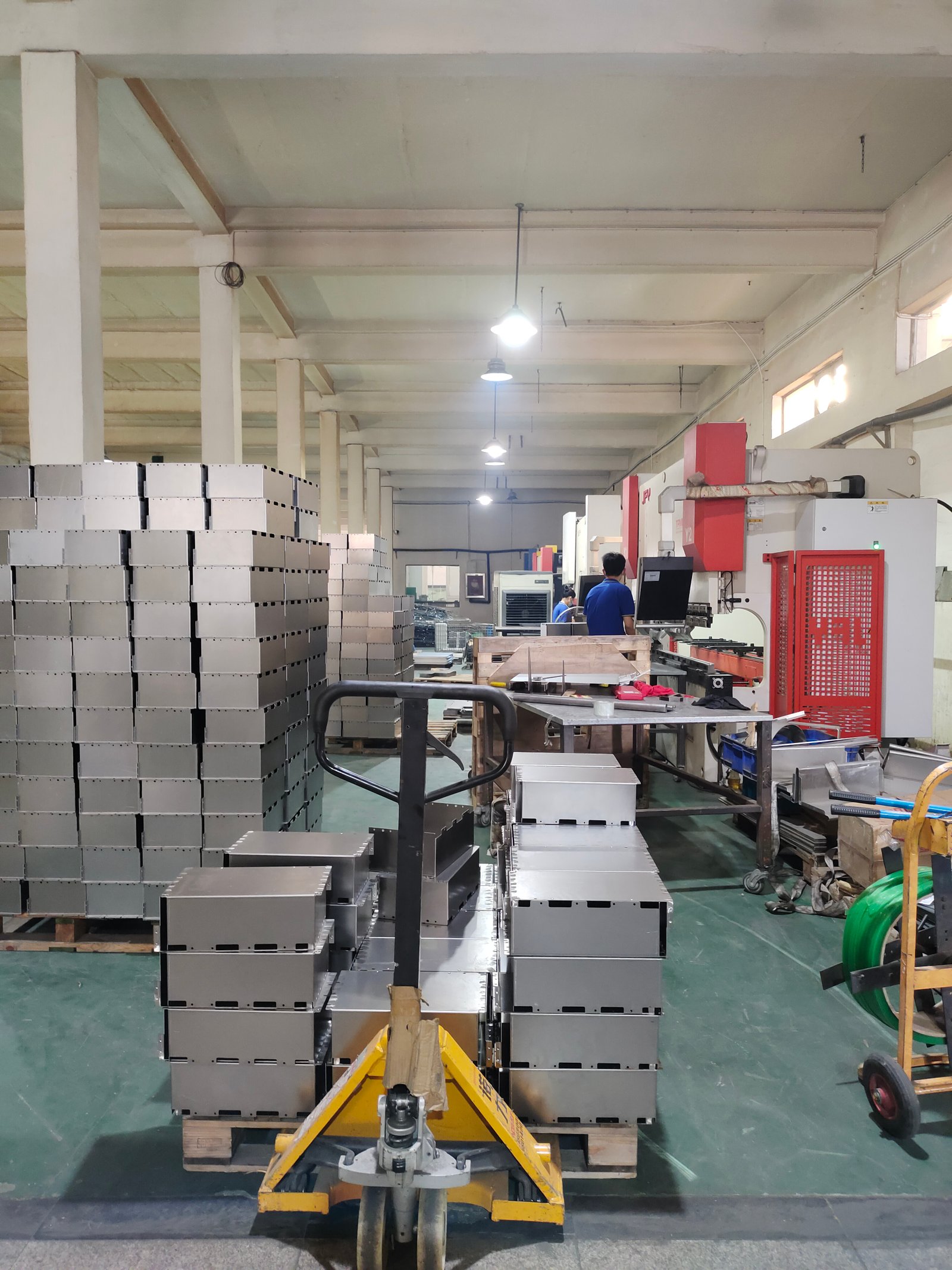
The 12-Point DFM Checklist
1. Material: standard gauge, standard grade, available from stock
The question: Is the specified material a standard gauge (1.0, 1.2, 1.5, 2.0, 2.5, 3.0 mm) and a common grade (CRS, SS304, SS316, 5052, 6061, galvanized) that the factory can source quickly?
Why it matters: Non-standard gauges or exotic grades trigger minimum order quantities, longer lead times, and 20–50% material price premiums. We stock 1.0/1.2/1.5/2.0 mm in cold-rolled steel, stainless 304, and aluminum 5052 — anything outside this list is special order.
Action: If your design calls for 1.7 mm stainless 316L, ask us if 1.5 mm 304 will work. It usually does, at a lower cost.
2. Bend radius: ≥ material thickness
The question: Is the inside bend radius equal to or greater than the material thickness?
Why it matters: This is the “air bend” sweet spot. Smaller radii require bottom-die bending, which is slower, more expensive, and can crack the material on stainless and aluminum. Larger radii need a wider die and may not be necessary for strength.
Action: Specify inside bend radius = material thickness unless you have a specific reason. For aesthetic, large-radius bends, allow at least 2× thickness.
3. Bend direction: consistent, with sequence in mind
The question: Are all bends in the same direction? Have you thought about bend sequence?
Why it matters: Bends that alternate directions force the operator to flip the part repeatedly, increasing handling time and risk of error. Bend sequence determines which features are accessible at each step.
Action: Design bends in one direction where possible. For complex parts, add a bend sequence callout or ask us to recommend one during DFM.
4. Hole size: ≥ material thickness for clean cuts
The question: Is every hole diameter at least equal to the material thickness?
Why it matters: Below material thickness, laser and punch cutting produce slag, taper, and edge damage. Tapped holes need at least 1.5× thickness diameter to avoid tap breakage.
Action: If you need a small hole, plan to drill it as a secondary op. Specify “laser cut pilot + drill to size” if needed.
5. Slot and cutout corners: radiused, not square
The question: Do all internal corners in slots and cutouts have a specified radius (≥ 1.5 mm for steel, ≥ 1× thickness for harder materials)?
Why it matters: Square internal corners are impossible to cut cleanly. A small radius prevents tool overload, gives cleaner edges, and avoids the “burn mark” at the corner.
Action: Add explicit R callouts on every internal corner of every cutout. Don’t leave it implied.
6. Edge distance: hole-to-edge ≥ 1.5× thickness
The question: Is the distance from any hole center to the nearest edge at least 1.5× material thickness?
Why it matters: Holes too close to an edge deform during cutting and bending. The minimum practical edge distance is material thickness, the safe minimum is 1.5× thickness, and ideal is 2× or more.
Action: If you need a hole close to an edge, plan a relief feature (a small slot or extra material) and machine it away in a secondary op.
7. Tolerances: tight on interfaces, standard elsewhere
The question: Are tolerances specified per-feature, with the tightest only on parts that mate with other components?
Why it matters: Tight tolerances multiply cost. ±0.1 mm might cost 2–3× more than ±0.3 mm on the same feature. A drawing with ±0.1 mm on every dimension will get a much higher quote than a drawing with selective tolerances.
Action: Use general tolerance notes for the bulk of the drawing (±0.3 mm for dimensions, ±0.2 mm for hole positions, ±1° for angles) and call out specific tighter tolerances only where they matter — usually on hole patterns that mate to other parts.
8. Finish: specified, with the geometry to support it
The question: Is the finish specified (powder coat RAL, anodize type, plating, etc.), and does the geometry account for the finish thickness?
Why it matters: Different finishes add different thicknesses. Powder coat 80–120 μm, galvanizing 50–150 μm, anodizing 5–25 μm, wet paint 25–40 μm. Small holes, threads, and tight fits may need oversizing or masking.
Action: Specify finish in the title block. For powder coat and galvanizing, don’t design holes smaller than 4 mm. For mating parts, account for the film thickness in your tolerances.
9. Hardware: standard sizes, ideally self-clinching
The question: Are the fasteners standard sizes (M3, M4, M5, M6, M8, #6-32, #8-32, #10-32, 1/4-20)? Can you use self-clinching studs or standoffs?
Why it matters: Self-clinching hardware (PEM-style) installs in one press operation and is more reliable than separate nuts in a pocket. Non-standard hardware is harder to source and slower to install.
Action: Use standard metric or imperial sizes. Replace “M3 nut in a pocket” with “M3 self-clinching stud.”
10. Welding: clear callouts, accessible joints
The question: If the part is welded, are the welds called out per AWS or ISO standard? Can a weld torch physically access each joint?
Why it matters: A weld callout that just says “weld here” is asking for trouble. Without a spec, every welder will interpret it differently. Inaccessible joints cause porosity, undercut, and missed fusion — all of which fail inspection.
Action: Use AWS D1.1 (steel), D1.2 (aluminum), D1.6 (stainless), or ISO 9606. Specify weld size, type (fillet, butt, plug), and inspection. If the joint is hard to access, redesign it.
11. Assembly: oriented, KD-friendly, with hardware called out
The question: If the part is a sub-assembly, is the orientation obvious? Is hardware called out in a bill of materials? Is the design knock-down (KD) friendly for shipping?
Why it matters: Parts that can be assembled in two orientations get assembled in the wrong one. Hardware without part numbers gets lost. Bulky welded assemblies cost 3–4× more to ship than flat-pack KD designs.
Action: Add asymmetry (an obvious “this side up” feature). Provide a BOM with hardware called out. Design for flat-pack where possible.
12. Inspection: how will the factory prove the part is correct?
The question: How will the factory demonstrate that the part meets your drawing? What inspections, what reports, what documentation?
Why it matters: “Inspect per drawing” is not a complete inspection plan. CMM on critical dimensions? Visual on cosmetic surfaces? Functional test on moving parts? Salt spray on the finish? Each requires specific equipment and time.
Action: Specify inspection requirements explicitly: AQL level, dimensional inspection scope, finish testing (salt spray hours, adhesion test), functional test (if applicable). This makes quality discussions objective instead of subjective.
How to use this checklist
Three ways, in increasing depth:
- Self-review: Run your own drawing through these 12 points before you send it. If you can answer “yes” to all 12, you’re 90% of the way to a clean OEM project.
- Pre-RFQ review: Send the checklist to your engineering team with the drawing. Have them mark any “no” or “unsure” answers. Fix those before sending the RFQ.
- Pre-production review: Send the checklist with the drawing to your OEM factory. Ask them to mark any issues. This is the most thorough use and is what we do for free on every RFQ at Fulei Metal.
What we do with this checklist
At Fulei Metal, we run every RFQ through this 12-point review and send the customer a written DFM report. If everything checks out, you get a green light and a quote. If there are issues, you get:
- A bullet list of the issues we found
- For each issue, a recommendation (change X to Y, or “we can work around this”)
- A revised quote based on the recommended changes
You can accept or reject the recommendations. We work with you either way. But in our experience, 80% of customers accept at least some of the recommendations, and they always save money on the resulting production run.
When you don’t need this checklist
Honestly, if you’re a high-volume OEM buyer with a mature, well-engineered part, you’ve already done most of this work. Your drawings will be tight, your tolerances will be correct, your finish will be specified. The checklist is mainly for:
- First-time designs where the team is still learning
- Prototypes that are heading toward mass production
- Designs from engineers who are new to sheet metal (vs. machining or plastic injection)
- Anyone who’s ever had a part come back from a factory with problems that should have been caught at design
The bigger principle
DFM is not about compromising your design. It’s about designing in a way that gets the same functional outcome with less cost, less time, and less risk. Every rule on this checklist exists because someone, somewhere, learned the hard way that ignoring it causes problems.
Apply the checklist. Send us your drawing. Get a free DFM review. Save yourself the headache of a 30% defect rate on the first production run.
That’s what we’re here for.
Get a Free DFM Review
Send us your drawing (STEP, DXF, or PDF) and we’ll run it through this 12-point checklist. Free, no obligation, reply within 24 hours.