
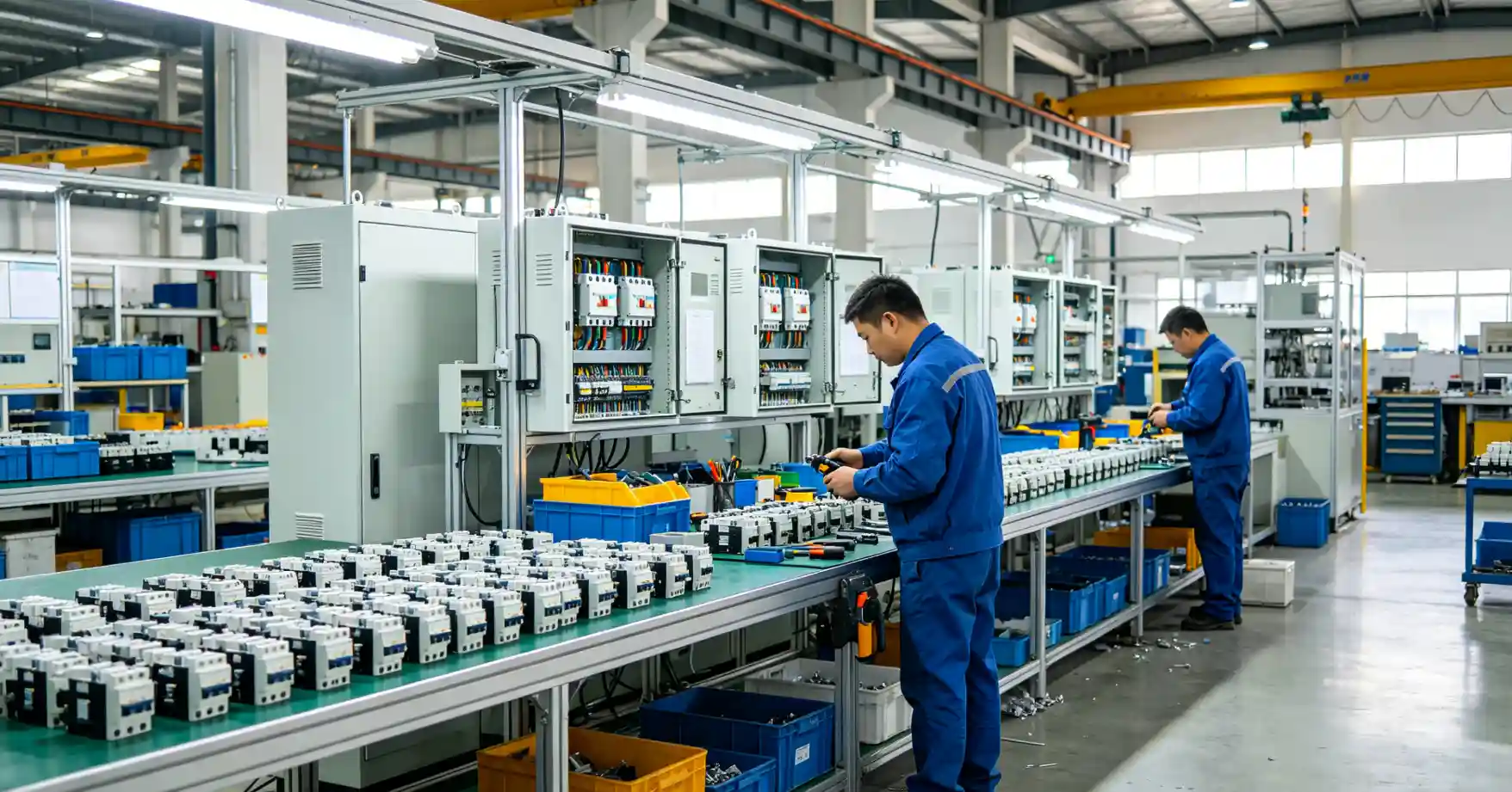
At Fulei Metal, we don’t just fabricate sheet metal parts — we assemble them into finished products. Our assembly department builds everything from simple two-piece brackets to complete electrical enclosures with wiring, gaskets, and hardware installed. We’ve assembled hundreds of thousands of units, and we’ve learned that assembly cost isn’t determined on the assembly line — it’s determined in the design. Here are eight DFA rules we apply to every project, with real examples of the cost difference they make.
Rule 1: Minimize part count by integrating features
Every separate part adds cost: you buy it, inventory it, handle it, orient it, and fasten it. The DFA methodology by Boothroyd and Dewhurst estimates that each fastener adds 3–6 seconds to assembly time — but the real cost is higher when you include the part cost, the purchased-part QC, and the risk of missing hardware in the kit.
Practical example: A customer’s bracket originally had three separate pieces: a main plate, a small stiffener rib, and a mounting flange — joined with six M4 screws and nuts. We redesigned it as a single piece with the stiffener formed from a bend flange, and the mounting tab integrated into the blank. The result: three pieces became one, six fasteners became zero assembly steps, and the unit cost dropped from ¥42 to ¥18. The stamped part was slightly more expensive than the original flat plate, but eliminating assembly labor and hardware more than covered it.
The DFA question to ask: Can this feature be formed from the same blank instead of being a separate part? Bend tabs, embossments, louvers, and drawn holes can replace separate brackets and spacers.
Rule 2: Use self-locating features (tabs and slots)
When an assembler has to measure and align two parts by hand, every assembly is slightly different — and every assembly takes extra time. Self-locating features — tabs on one part that fit into slots on the mating part — eliminate the measurement step entirely. The parts snap into the correct position.
Practical example: A UK customer’s electronics enclosure had a back panel that required alignment within ±0.5 mm before the assembler could drive the mounting screws. Our redesign added two 6 mm tabs on the back panel that fit into 6.2 mm slots on the enclosure body. The assembler now drops the panel in — the tabs locate it — and drives the screws without touching a ruler. Assembly time dropped from 45 seconds to 18 seconds per unit. Over 5,000 units, that’s 37 hours of labor saved.
Tab-and-slot design guidelines from our experience: the tab should be 0.1–0.2 mm narrower than the slot for a slip fit, and the tab length should be at least 2× the material thickness for adequate engagement. The tab and slot are cut during laser cutting at zero added cost.
Rule 3: Design for top-down assembly (gravity helps)
If an assembler has to hold a part in place while fastening it — fighting gravity — assembly takes longer and quality drops. Parts should be placed from above, resting on the subassembly below them, so gravity holds them in position during fastening.
Practical example: A Korean customer’s display mounting bracket originally required the top plate to be held from underneath while the assembler drove four screws from above — a two-handed operation with the assembler’s arm in an awkward position. By flipping the assembly sequence so the base plate was the bottom layer and the bracket was added on top, the assembly became a one-handed operation: drop the bracket on, gravity holds it, drive the screws. Cycle time dropped from 35 seconds to 22 seconds, and the assembler’s fatigue (and error rate) decreased measurably.
This rule also means: design the base or chassis as the first component in the stack, and add components in vertical layers. Never design an assembly where the heaviest component must be held overhead.
Rule 4: Standardize fasteners — fewer sizes = fewer tools
Every unique fastener size requires its own driver bit, its own torque setting, and its own inventory. An assembler who has to switch between M3, M4, M5, and M6 fasteners on the same product will spend more time changing tools than driving screws.
Practical example: We reviewed a US customer’s enclosure that used M3 screws for the cover, M4 screws for internal brackets, M5 bolts for the mounting feet, and #10-32 UNC threaded inserts for cable glands — four sizes, two thread standards. We proposed reducing to two sizes: M4 for all internal and cover mounting (the M3 locations had enough edge distance for the larger screw), and M6 for the feet (the structural loads were higher than M5 could handle anyway). The hardware count went from four SKUs to two. Assembly time dropped 15%. The assembler now uses one T20 Torx bit for the entire product.
Our standard recommendation: no more than two fastener sizes per product. If the design forces three sizes, there’s usually a simplification opportunity.
Rule 5: Use captive fasteners (PEM inserts) instead of loose nuts
Loose nuts require the assembler to hold the nut behind the panel while driving the screw from the front — a two-handed operation that’s slow and error-prone. PEM self-clinching fasteners (inserts, studs, standoffs) are pressed into the sheet metal during fabrication and stay there permanently.
Practical example: A Japanese customer’s equipment panel had 14 M4 through-holes with loose M4 nuts and flat washers behind each. Assembly required 14 × 2 separate pieces (nut + washer) that had to be positioned, held, and fastened. We switched to M4 PEM nuts installed in the panel at the press — a 5-second operation per insert during fabrication. The assembly step dropped from 14 × 8 seconds (loose hardware) to 14 × 3 seconds (screw-only), saving 70 seconds per unit. Over 2,000 units per year, that’s 39 hours of assembly labor saved.
PEM inserts cost ¥0.20–0.80 each in volume, installed. A loose M4 nut + washer costs ¥0.05. On the BOM, the PEM looks more expensive — but the assembly labor savings typically cover the PEM cost 5–10× over.
Rule 6: Design for robotic/hand access (clearance for tools)
A design may look great in CAD but be impossible to assemble when the screwdriver can’t reach the screw. We see this constantly: fasteners buried behind flanges, inside deep pockets, or positioned so close to a vertical wall that no tool fits.
Practical example: A customer’s enclosure had M4 screws located 12 mm from a vertical side wall. Our electric screwdriver body diameter is 35 mm — it couldn’t reach. The assembler was using an L-shaped Allen key by hand, taking 10–12 seconds per screw versus 2–3 seconds with a power driver. We moved the mounting holes 25 mm from the wall (keeping the same flange width by adjusting the bend radius). The power driver now fits, and the assembler saves 8 seconds × 12 screws = 96 seconds per unit.
Clearance guidelines we use: allow at least 5 mm radial clearance around the fastener centerline for the driver bit, plus the driver body diameter for the approach path. For M3-M5 fasteners, keep the nearest obstruction at least 25–30 mm from the fastener centerline. For deep-reach fasteners (more than 50 mm from the access face), use a hex-head bolt with a socket driver instead of a Phillips screw.
Rule 7: Eliminate reorientation during assembly
Every time the assembler has to flip the part over or rotate it to access a different face, the assembly process loses 3–5 seconds and gains a risk of damage or error. Ideally, the part is assembled from one side, in one orientation, with all fasteners accessible without reorientation.
Practical example: A European customer’s control box originally had mounting screws on four faces: front (8 screws), back (4 screws), top (2 screws), and bottom (4 screws). The assembly sequence required three reorientations per unit. By redesigning the enclosure to use PEM standoffs on the cover and internal bracket — all accessible from the front — we eliminated the back and bottom fasteners entirely. The assembler now works exclusively from the front face, in one orientation, and the assembly time dropped from 3.5 minutes to 1.8 minutes per unit. Quality improved too — the error rate on back-side fasteners (missed screws) went from 1.2% to zero.
This rule extends to workstation design: if a part absolutely needs two-sided access, use a rotating fixture so the assembler doesn’t have to lift and flip a 15 kg assembly.
Rule 8: Use Poka-Yoke (mistake-proofing) features
Poka-Yoke — a Japanese term for mistake-proofing — means designing the part so it can only be assembled correctly. If the part can be installed backwards, upside-down, or in the wrong orientation, someone will eventually do it. A well-designed part has physical features that prevent incorrect assembly.
Practical example: A bracket that mounted to an enclosure had four mounting holes in a nearly-square pattern (50 × 52 mm). The assembler was supposed to orient the bracket with the longer spacing horizontally, but the 2 mm difference was invisible at a glance. About 3% of units were assembled with the bracket oriented wrong — caught at final inspection and requiring disassembly and rework.
We added a small 5 mm alignment tab on one edge of the bracket that fit into a corresponding notch on the enclosure. The bracket now only fits one way. If the assembler tries to install it backwards, the tab hits a flat edge and the holes don’t line up. The mistake rate dropped to zero immediately. Cost: one laser-cut feature, zero added part cost. Savings: 3% rework eliminated, which for 5,000 units/year was 150 rework events at ~5 minutes each — 12.5 hours of labor per year recovered.
Common Poka-Yoke features in sheet metal: asymmetric hole patterns (one hole offset by 5 mm), alignment tabs and notches, different-sized holes for different-sized fasteners, and color coding on temporary assembly fixtures. The key principle: the assembler should not need to read a drawing to know which way the part goes — the part itself should tell them.
What these rules mean for your project cost
In our factory, assembly labor is ¥30–40 per hour depending on skill level. If a product takes 5 minutes to assemble at ¥35/hour, the assembly labor is ¥2.92 per unit. If you sell 10,000 units per year, that’s ¥29,200 in assembly labor annually. Cut the assembly time to 2.5 minutes through DFA, and you save ¥14,600 per year — every year, for the life of the product.
But the real savings are often larger: fewer parts to purchase and inventory, fewer missed fasteners to catch at QC, fewer rework events, and smoother production scheduling. We’ve seen DFA redesigns reduce total product cost by 20–40% when assembly was a significant portion of the BOM.
The best time to apply DFA is before the first prototype is made. If you send us a drawing at the design stage, we’ll review it for assembly efficiency — not just manufacturability — and suggest changes that cost nothing to implement in the design but save money on every unit built. Send us your drawing and we’ll include a free DFA review with your quote.
Get a Free DFA Review With Your Quote
Send us your drawing before you finalize the design. We’ll include a Design for Assembly review — tab-and-slot suggestions, fastener rationalization, and assembly sequence optimization — at no charge.