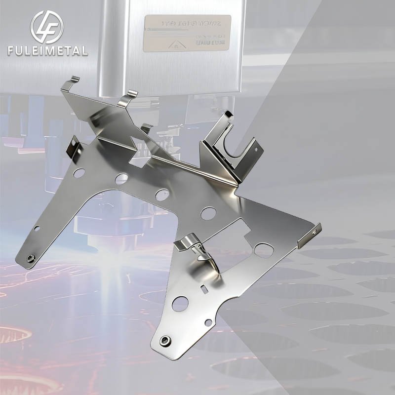
The Science & Art of Sheet Metal Bending: How This Fundamental Fabrication Process Works
If you’ve ever held a metal bracket, a laptop chassis, or a kitchen range hood, you’ve touched a product shaped by sheet metal bending—one of the most essential processes in sheet metal fabrication. It’s the magic that turns flat metal sheets into 3D parts with angles, folds, and curves. But how exactly does bending transform a flat piece of metal into a structured component? Let’s break down the working 原理,key terms, and what makes a bend successful.
What Is Sheet Metal Bending, Anyway?
At its core, sheet metal bending is a cold forming process (no extreme heat required) that uses force to bend a flat metal sheet along a predetermined line (the “bend line”) into a desired angle (e.g., 90°, 45°, 135°). Unlike cutting or punching, which remove material, bending reshapes it—preserving the sheet’s original thickness (a golden rule of sheet metal design!) while creating the 3D geometry needed for functional parts.
The Basic Mechanics: How Bending Works
Bending might look simple from the outside, but it relies on precise physics and tooling to avoid cracks, warping, or inconsistent angles. Here’s a step-by-step breakdown of the process:
1. Tool Setup: The “Punch & Die” Duo
Every bending operation uses two key tools—think of them as a team:
- Punch: The upper tool that applies downward force. It has a rounded tip (matching the desired bend radius) that presses into the metal.
- V-Die: The lower tool with a V-shaped groove. The metal sheet sits on top of the V-die, and the punch pushes it into the groove to create the bend.
The width of the V-die’s groove (called the “V-opening”) is critical—it’s usually 6–12 times the material thickness (e.g., a 2mm thick sheet uses a 12mm V-opening). A wider V-opening reduces stress on the metal, while a narrower one gives sharper bends (but risks cracking).
2. The Bending Action: From Flat to Angled
When the press (either a hydraulic, mechanical, or pneumatic press brake) activates:
- The punch descends and makes contact with the flat metal sheet, centered over the V-die’s groove.
- As force increases, the metal bends downward into the V-die. The material isn’t just “folding”—it’s undergoing plastic deformation: the outer layers of the bend stretch (tension), while the inner layers compress (compression).
- A “neutral axis” forms between the stretched and compressed layers. This is the only part of the metal that doesn’t change length during bending—and it’s key to calculating the flat pattern (more on that later!).
- Once the desired angle is reached, the punch retracts. The metal “springs back” slightly (a natural reaction to being bent), so operators often over-bend by 1–5° to compensate (e.g., bending to 93° to get a final 90° angle).
Key Terms Every Designer (and Curious Maker) Should Know
To truly grasp bending, you need to speak its language. Here are the most critical terms:
- Bend Radius (R): The radius of the curve at the bend. You can’t have a “sharp” bend (R=0)—even the tightest bends have a small radius. As we covered earlier, the interior bend radius should be at least equal to the material thickness to avoid cracking.
- Bend Angle (θ): The angle of the bend (e.g., 90° for a right angle).
- Bend Allowance (BA): The extra length of material needed to account for stretching during bending. Calculate it using the neutral axis, and you’ll get an accurate flat pattern (no undersized or oversized parts!).
- K-Factor: A constant that describes where the neutral axis sits relative to the material thickness (K = distance from inner surface to neutral axis / material thickness). It varies by material (e.g., aluminum has a lower K-factor than stainless steel) and bend radius.
- Springback: The amount the metal “relaxes” after bending. Harder materials (like 304 stainless steel) have more springback than softer ones (like 6061 aluminum), so they need more over-bending.
Why Bending Matters (and Common Mistakes to Avoid)
Bending is everywhere because it’s cost-effective, fast, and versatile—but it’s not foolproof. Here are the biggest pitfalls designers and fabricators face, and how to fix them:
- Too-Tight Bend Radius: A radius smaller than the material thickness causes cracks in the outer stretch zone. Stick to R ≥ T (thickness) for safety.
- Holes Too Close to Bends: Holes within 2× the material thickness of a bend line will distort or tear. Keep them far enough away!
- Ignoring Springback: Forgetting to over-bend leads to angles that are too shallow (e.g., 87° instead of 90°). Always check the material’s springback rate.
- Asymmetric Bends: Lopsided bend layouts cause warping. Balance bends symmetrically when possible.
Wrapping Up: Bending = Form + Function
Sheet metal bending is a perfect blend of physics and practicality. It turns flat sheets into strong, lightweight parts that power industries from automotive to aerospace. Whether you’re designing a simple bracket or a complex chassis, understanding how bending works helps you create parts that are easy to fabricate, cost-effective, and built to last.
Next time you pick up a bent metal part, take a second to appreciate the punch, die, and precision that turned a flat sheet into something functional—now you know the science behind the bend!
Got questions about bending for your next project? Drop a comment below, and we’ll break down how to optimize your design for the bending process.
 Read more about sheet metal optimization tips
more photos:https://fuleimetal.com/project-case/
#SheetMetal #package #MaterialOptimization #WeldingProcesses #WeldQuality

