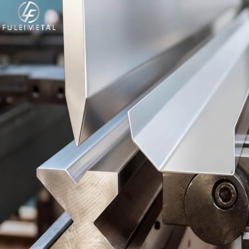
Custom Sheet Metal Bending Design Parameter Table for Common Materials
Below is a detailed, material-specific table outlining critical bending design parameters for three widely used sheet metals (aluminum 6061-T6, cold-rolled steel [CRS] 1018, and stainless steel 304). These values are based on industry standards and optimize for part integrity, production efficiency, and consistency. All dimensions are in millimeters (mm) unless noted, with “T” representing the material thickness.
| Parameter Category | Aluminum 6061-T6 (Soft-Medium Strength) | Cold-Rolled Steel (CRS) 1018 (Mild Steel) | Stainless Steel 304 (Austenitic, Low Carbon) | Notes |
|---|---|---|---|---|
| Minimum Bend Radius (R_min) | 0.5T | 1.0T | 1.5T | – Harder tempers (e.g., 6061-T8) require larger R_min (e.g., 1.0T).
– For stainless steel, R_min increases to 2.0T for thicknesses > 6mm. |
| Bend Line to Edge Distance | ≥1.5T | ≥1.5T | ≥2.0T | Prevents edge buckling/tearing. For edges with sheared (not deburred) finishes, increase to 2.0T. |
| Bend Line to Hole/Cutout Distance | ≥2.0T | ≥2.0T | ≥2.5T | Avoids hole distortion or material splitting. For holes ≤ 3mm diameter, increase to 2.5T (aluminum/CRS) or 3.0T (stainless steel). |
| Inside Bend Angle Tolerance | ±1° | ±1° | ±1.5° | Tighter tolerances (±0.5°) are possible with precision tooling but increase cost. |
| Flat Pattern Length Tolerance | ±0.1mm + 0.005×T | ±0.1mm + 0.005×T | ±0.15mm + 0.008×T | Accounts for bend allowance/deduction variations. Larger parts (>300mm) may have ±0.2mm tolerance. |
| Recommended Bend Sequence Priority | 1. Large outer bends
2. Small inner bends 3. Close-tolerance features |
Same as aluminum | Same as aluminum, but allow extra tool clearance for harder material | Avoid nesting bends (inner bends blocked by outer bends) — critical for stainless steel due to tool wear. |
| Maximum Bend Height (Per Operation) | Up to 300mm (depends on press brake capacity) | Up to 350mm | Up to 300mm | Limited by press brake tooling length and material rigidity. For taller bends, split into multiple operations. |
Example Calculations for Key Parameters
To illustrate how these values apply in practice, here are examples for a T=2mm sheet of each material:
| Material | Minimum Bend Radius (R_min) | Bend Line to Edge Distance | Bend Line to Hole Distance |
|---|---|---|---|
| Aluminum 6061-T6 | 0.5×2 = 1mm | 1.5×2 = 3mm | 2.0×2 = 4mm |
| CRS 1018 | 1.0×2 = 2mm | 1.5×2 = 3mm | 2.0×2 = 4mm |
| Stainless Steel 304 | 1.5×2 = 3mm | 2.0×2 = 4mm | 2.5×2 = 5mm |
Would you like to:
- Add another material (e.g., galvanized steel, aluminum 5052) to this table?
- Get a step-by-step example of calculating bend allowance/deduction for one of these materials?
- Convert the table to inches or adjust parameters for a specific thickness (e.g., T=5mm)?
more photos:https://fuleimetal.com/project-case/
#SheetMetal #package #MaterialOptimization #WeldingProcesses #WeldQuality

